Eureka AIR delivers breakthrough ideas for toughest innovation challenges, trusted by R&D personnel around the world.

Heavy-load wheel type robot adjustable suspension device

A wheeled robot and suspension device technology, applied in the field of robotics, can solve the problems such as the inability to adjust the up and down stroke of the suspension more accurately, and achieve the effects of increasing the passability of the chassis, improving the ability to maintain attitude, and improving the passability of the chassis

Pending Publication Date: 2018-03-06
HANGZHOU JIMU TECH CO LTD
View PDF0 Cites 6 Cited by
  • Summary
  • Abstract
  • Description
  • Claims
  • Application Information

AI Technical Summary

Problems solved by technology

The existing technology can only perform barriers and shock absorption to a certain extent, but cannot achieve a more accurate adjustment of the up and down stroke of the suspension

Method used


Image

  • Heavy-load wheel type robot adjustable suspension device
  • Heavy-load wheel type robot adjustable suspension device
  • Heavy-load wheel type robot adjustable suspension device

Examples


Embodiment 1

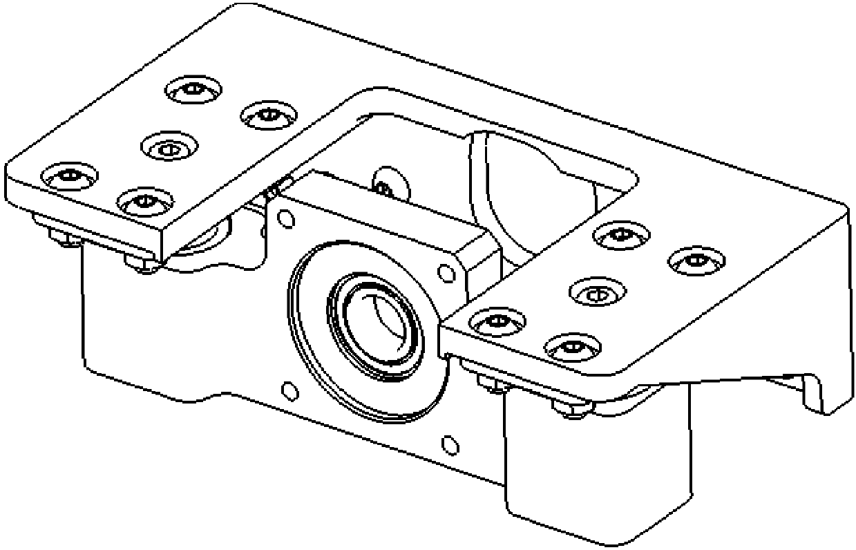
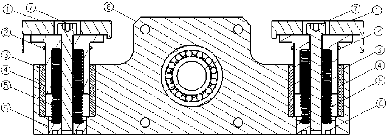
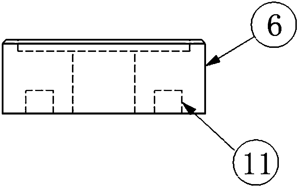
[0027] like figure 1 , 2 As shown, an adjustable suspension device for a heavy-duty wheeled robot provided in this embodiment includes a suspension support 8, the suspension support 8 adopts a symmetrical design, and a guide groove is opened on each side, and the groove wall serves as a guide The fixed end of the device; the mobile end 4 of the guide device is fixedly connected with the frame 9 through the adapter seat 1; The sliding bearings 3 slide between the seats 8, so that the sliding bearings 3 can be used to slide up and down, and the moving end 4 of the guide device and the suspension support 8 can be used to protect the sliding bearings 3 from radial damage. The spring 5 is used as the elastic element, the upper end of the spring 5 is inserted into the inner cavity of the moving end 4 of the guide device, supported by the inner cavity wall, and the lower end is only supported by the lead adjustment block 6; the lead adjustment block 6 is installed on the suspension ...

Embodiment 2

[0040] An adjustable suspension device for a heavy-duty wheeled robot provided in this embodiment includes a suspension support 8 on which an independent fixed end of the guiding device is arranged; the moving end 4 of the guiding device is directly fixed to the frame 9 Connection; the moving end 4 of the guiding device is in contact with the fixed end of the guiding device through a linear bearing; the spring 5 is used as the elastic element, the upper end of the spring 5 is inserted into the inner cavity of the moving end 4 of the guiding device, supported by the inner cavity wall, and the lower end is only adjusted by the lead The block 6 is supported; the lead adjustment block 6 is installed in the lead adjustment block installation hole of the suspension support 8, and can move along the lead direction; the adjustment rod 7 passes through the moving end 4 of the guide device and the spring 5, and the upper end is covered with a nut , through the nut limit, the limit guidin...


PUM


Abstract

The invention discloses a heavy-load wheel type robot adjustable suspension device which comprises a suspension support. Guide device fixed ends are arranged on the suspension support. The upper endsof elastic elements are sleeved with inner cavities of guide device movable ends and supported through the inner cavity walls, and the lower ends of the elastic elements are only supported through lead adjusting blocks. The lead adjusting blocks are installed in lead adjusting block installation holes of the suspension support and can move in the lead directions. By the adoption of the suspensiondevice, through change of the compression amount of springs of a suspension and the relative positions of upper peaks and lower peaks of the springs of the suspension, the ground clearance of a robotis changed, the chassis passing ability is improved, and the capacity of penetrating the bottom of a vehicle or an obstacle is improved; according to the evenness condition of an actual running road surface of the wheel type robot, the rigidity of the suspension can be increased, and the pose keeping ability of the robot moving on the uneven road surface is improved; and the suspension device is particularly suitable for the ultrathin wheel type robot.

Description

technical field [0001] The invention belongs to the technical field of robots, and in particular relates to an adjustable suspension device for a heavy-duty wheeled robot. Background technique [0002] Current wheeled robots mainly use flexible materials such as rubber or a fixed spring to achieve shock absorption. The prior art can only perform barrier and shock absorption to a certain extent, but cannot achieve a more accurate adjustment of the up and down stroke of the suspension. Contents of the invention [0003] The object of the present invention is to provide an adjustable suspension device for a heavy-duty wheeled robot aiming at the deficiencies of the prior art. [0004] The purpose of the present invention is achieved through the following technical solutions: an adjustable suspension device for a heavy-duty wheeled robot, including a suspension support, a fixed end of a guide device is arranged on the suspension support, and the mobile end of the guide device...

Claims


Application Information

Patent Timeline
Patent Type & Authority Applications(China)
IPC IPC(8): B60G17/02
CPCB60G17/02B60G2204/40
Inventor 曹力王晨郭雨
Owner HANGZHOU JIMU TECH CO LTD
Why Eureka
Eureka Blog
Learn More