
Compact liquefied natural gas immersed pump guide vane structure

A technology for liquefied natural gas and submersible pumps, which is applied to pumps, pump components, non-variable-capacity pumps, etc., can solve problems such as unfavorable rear-stage impeller performance, increase the overall manufacturing cost, reduce the efficiency of the whole pump, etc., and achieve a compact structure design. , reduce hydraulic loss, reduce the effect of impact

Pending Publication Date: 2018-03-06
JIANGSU UNIV +1
View PDF12 Cites 2 Cited by
  • Summary
  • Abstract
  • Description
  • Claims
  • Application Information

AI Technical Summary

Problems solved by technology

[0005] In order to solve the above problems, this patent invented a compact LNG submersible pump guide vane structure, which replaces the existing traditional LNG submersible pump guide vane, and solves its large hydraulic loss, large impact on the flow channel, and large radial size. It increases the overall manufacturing cost, is not conducive to the effective performance of the impeller of the rear stage, and reduces the technical defects such as the efficiency of the whole pump

Method used


Image

  • Compact liquefied natural gas immersed pump guide vane structure
  • Compact liquefied natural gas immersed pump guide vane structure
  • Compact liquefied natural gas immersed pump guide vane structure

Examples


Embodiment 1

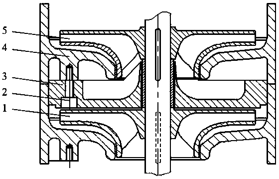
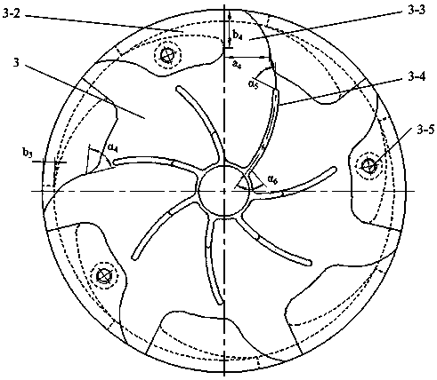
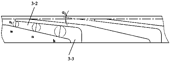
[0022] Embodiment one: if figure 2 As shown, the guide vane flow channel 3-2 is arc-shaped, and is evenly distributed on the same circumference of the outer edge of the guide vane body 3-1. u R=K (velocity moment remains constant) regular flow characteristics, designed guide vane flow channel inlet placement angle α 3, Make the liquid enter the flow channel smoothly and reduce the impact. The liquid enters the guide vane back blade flow channel through the guide vane flow channel liquid outlet 3-3, the position of the guide vane flow channel liquid outlet 3-3 is similar to the guide vane back blade 3-4, and the liquid outlet angle is α 4 Placement angle α with guide vane back blade inlet 5 They are all designed according to the law that the velocity moment remains constant, so that the liquid can flow into the flow channel of the guide vane back blade better, reducing the impact loss and energy loss. Such as image 3 As shown, the guide vane flow channel 3-2 has a gradual...


PUM


Abstract

The invention relates to a compact liquefied natural gas immersed pump guide vane structure. The compact liquefied natural gas immersed pump guide vane structure comprises a first-stage impeller and asecond-stage impeller, a guide vane is arranged between the first-stage impeller and the second-stage impeller and comprises a guide vane body and a plurality of guide vane back blades, a plurality of guide vane flow channels are evenly distributed on the outer edge of the guide vane body in the axial direction, guide vane flow channel liquid inlets formed in the guide vane flow channels communicate with liquid flowing out of the first-stage impeller, a guide vane flow channel liquid outlet formed in each guide vane flow channel communicates with a guide vane back blade flow channel inlet formed by the corresponding two adjacent guide vane back blades, and each guide vane back blade flow channel outlet formed by the corresponding two adjacent guide vane back blades obliquely extends intoan inlet of the second-stage impeller. According to the compact liquefied natural gas immersed pump guide vane structure, an existing traditional LNG immersed pump guide vane is replaced, and the technical defects that hydraulic losses are high, shock to the flow channels is large, the radial size is large, the overall manufacturing cost is increased, effective achievement of the properties of thebackward-stage impeller is not facilitated, and the overall pump efficiency is decreased are overcome.

Description

technical field [0001] The invention relates to a guide vane structure of a compact liquefied natural gas submersible pump, belonging to the technical field of liquefied natural gas pumps. Background technique [0002] Clean energy LNG (liquefied natural gas), the main component is methane, colorless, odorless, non-toxic and non-corrosive, and its volume is about 1 / 600 of the same gaseous volume. As another form of energy converted from natural gas, LNG is an effective way of storage and transportation of natural gas, and has developed rapidly in recent years. In the process of transshipment and filling of liquefied natural gas, a large number of LNG submersible pumps are required. The submersible pump is a special vertical multi-stage centrifugal pump structure. [0003] The guide vane is one of the key flow-passing parts of the LNG pump. The main function of the guide vane is to collect the liquid thrown out of the impeller, convert the kinetic energy of the liquid into p...

Claims


Application Information

Patent Timeline
Patent Type & Authority Applications(China)
IPC IPC(8): F04D29/44
CPCF04D29/448
Inventor 张德胜王超超施卫东李启峰金永鑫张智伟陈斌黄学军
Owner JIANGSU UNIV
Learn More