Composition of micro structure of drainage device

A technology of drainage device and limiter, which is applied in the composition field of micro-movement structure, and can solve the problems of inability to accurately push against the micro-switch, inconvenient use, invalid micro-switch touch, etc.

Inactive Publication Date: 2018-03-06
东莞市东坑合利美电子电器有限公司
View PDF5 Cites 0 Cited by
  • Summary
  • Abstract
  • Description
  • Claims
  • Application Information

AI Technical Summary

Problems solved by technology

[0003] However, this prior art utilizes the suction force of the magnet to make the lever act on the principle of leverage, and pushes against the micro switch in a non-asymptotic manner. If the suction force of the magnet itself is reduced or the position is shifted, the lever may not be able to provide sufficient The downforce road, even unable to accurately push the micro switch, resulting in invalid touch of the micro switch, causing inconvenience in use

Method used


Image

  • Composition of micro structure of drainage device
  • Composition of micro structure of drainage device
  • Composition of micro structure of drainage device

Examples


Embodiment Construction

[0016] In order to describe in detail the technical features of the present invention, the following preferred embodiments are given and described as follows in conjunction with the accompanying drawings, wherein:

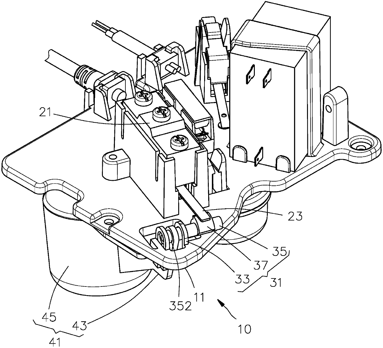
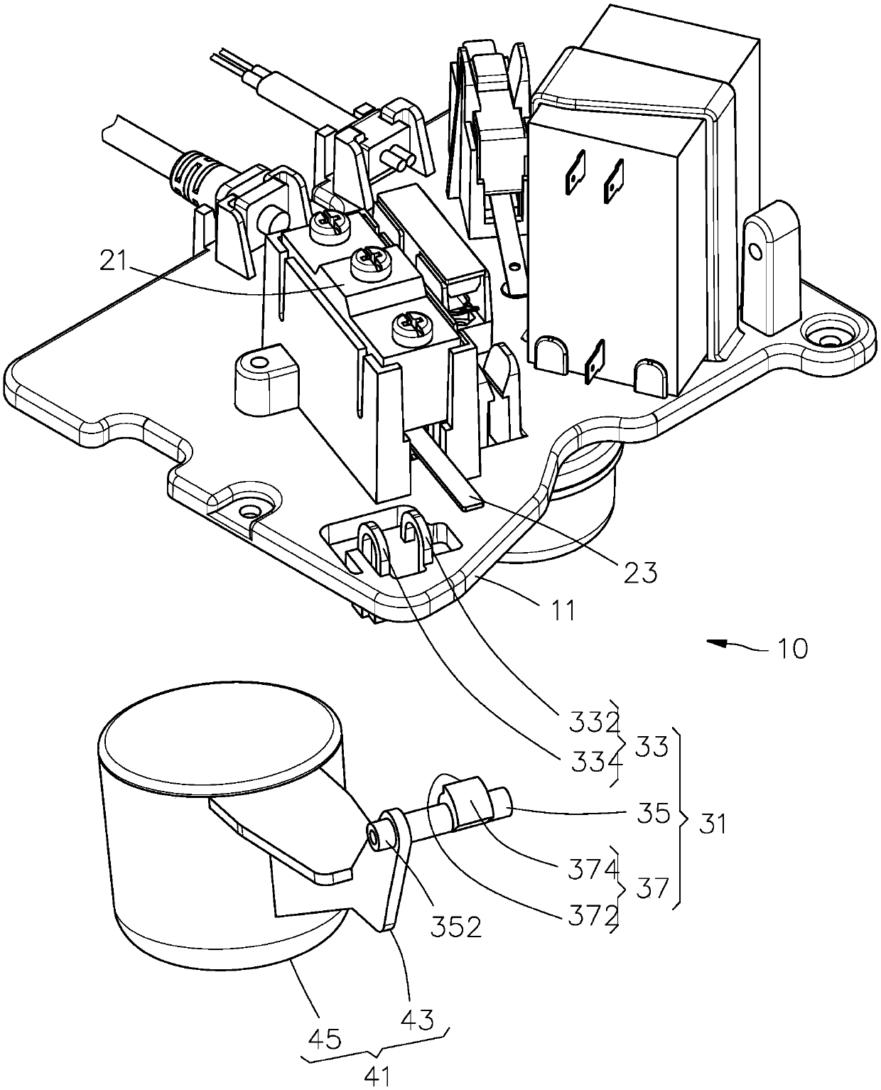
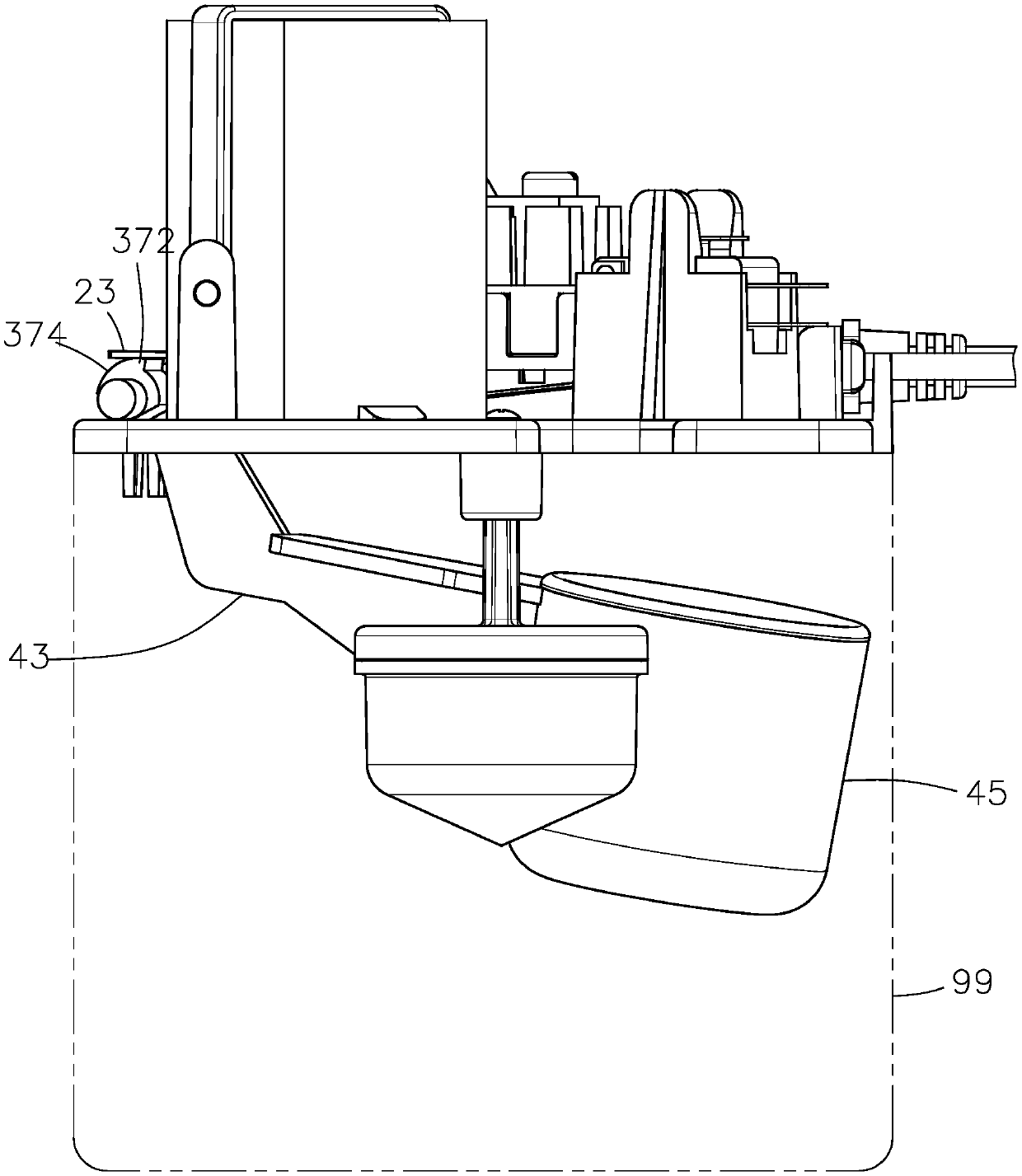
[0017] Such as Figure 1 to Figure 4 As shown, the composition 10 of the micro-movement structure of a drainage device provided by the present invention is mainly composed of a base plate 11, a micro-switch 21, an eccentric wheel group 31 and a buoy group 41, wherein:

[0018] The micro switch 21 is disposed on the substrate 11 , and the micro switch 21 is provided with a contact piece 23 .

[0019] The eccentric wheel set 31 has a fixed seat 33, a wheel shaft 35 and an eccentric wheel 37, the fixed seat 33 is arranged on the base plate 11, and the part body of the wheel shaft 35 is pivotally arranged on the fixed seat 33, and is fixed on the fixed seat 33. The wheel shaft 35 body of the seat 33 is defined as a connecting portion 352, and the other part of the whe...


PUM


Abstract

Composition of a micro structure of a drainage device involves a base plate, a micro switch, an eccentric wheel set and a float bowl set, wherein the micro switch is arranged on the base plate and provided with a touch press sheet; the eccentric wheel set is provided with a fixing seat, a wheel shaft and an eccentric wheel, the fixing seat is arranged on the base plate, one part of the body of thewheel shaft is arranged on the fixing seat in a pivoted mode, a connecting part is arranged in the position, located on the fixing seat, of the body of the wheel shaft, the eccentric wheel is arranged on the other part of the wheel shaft, and the outer edge of the eccentric wheel makes contact with the touch press sheet; and the float bowl set is provided with a rotary oscillating arm and a floatbowl, one end of the rotary oscillating arm is connected with the body of the float bowl, and the other end of the rotary oscillating arm is arranged on the connecting part. When swinging in a pivoted mode, the rotary oscillating arm drives the wheel shaft to rotate accordingly, and then the eccentric wheel is driven to rotate in a pivoted mode.

Description

technical field [0001] The present invention relates to a drainage device, in particular to the composition of a micro-movement structure of the drainage device. Background technique [0002] Please refer to China Taiwan Patent No. 278632, which is an improvement in the drainage structure of an air conditioner. When the water generated by the air conditioner gradually accumulates in the box, the position of the floating bucket will gradually rise upwards due to the buoyancy of the water. , when the amount of water accumulates to a certain height, the push tenon will push one end of the lever group, so that the free magnet of the lever group and the fixed magnet will be attracted and fixed, and then the other end of the lever group will press the micro switch and make The motor starts to drain water, and after the water level drops, the lever group is separated from the micro switch by the cord puller. Therefore, the above-mentioned prior art utilizes magnets and cords to con...

Claims


Application Information

Patent Timeline
Patent Type & Authority Applications(China)
IPC IPC(8): F24F13/22
CPCF24F13/222
Inventor 萧裕明
Owner 东莞市东坑合利美电子电器有限公司
Why Eureka
Try Eureka