Pneumatic arc striking device for vacuum cathode arc evaporation source

A technology of cathodic arc evaporation and arc striking device, which is applied in vacuum evaporation coating, ion implantation coating, metal material coating process, etc. The effect of air leakage, reducing defective product rate and improving production efficiency

Active Publication Date: 2018-01-05
DONGGUAN HUICHENG VACUUM TECH
View PDF3 Cites 0 Cited by
  • Summary
  • Abstract
  • Description
  • Claims
  • Application Information

AI Technical Summary

Problems solved by technology

[0005] The commonly used arc striking device has the following disadvantages when in use: 1) The piston extension rod 1-4 will generate heat when passing a large current during arc striking, especially in the vacuum chamber for a long time when it is subjected to heat radiation for a long time, the temperature rises, and the temperature rise of the piston extension rod It is directly transmitted to the insulating and sealing components on the sleeve, namely the sealing insulator 1-6, the dynamic seal 1-7 and the dynamic sealing pressure pad 1-8
The first to bear the brunt is the sealing insulating part 1-6, which is generally made of polytetrafluoroethylene, which is often deformed under long-term heating, and is easily damaged between the connecting flange 1-5 of the arc evaporation source and the piston extension rod 1-4 The vacuum seal, there is an air leakage problem
[0006] 2) The piston extension rod 1-4 is long, and the middle positioning is only through the rubber or plastic sealing insulation 1-6, which cannot achieve a good collimation effect, and the piston extension rod 1-4 will oscillate in space, resulting in The contact between arc striker 1-2 and target block 1-1 is shifted
[0007] 3) The piston extension rod 1-4 and the piston assembly 1-11 are connected by the connecting screw 1-9. Under the vibration impact of the piston assembly 1-11 moving back and forth, the connecting screw 1-9 will be loosened, that is, the piston extension rod 1-4 will rotate and move forward, and then drive the arcing needle 1-2 to rotate and migrate, causing the position of the arcing needle 1-2 to shift and increasing the distance between the arcing needle 1-2 and the surface of the target block 1-1 , so that the arc striking needle 1-2 elbow cannot touch the surface of the target block 1-1 and the arc cannot be struck. It must be adjusted by breaking the vacuum

Method used


Image

  • Pneumatic arc striking device for vacuum cathode arc evaporation source
  • Pneumatic arc striking device for vacuum cathode arc evaporation source
  • Pneumatic arc striking device for vacuum cathode arc evaporation source

Examples


Embodiment Construction

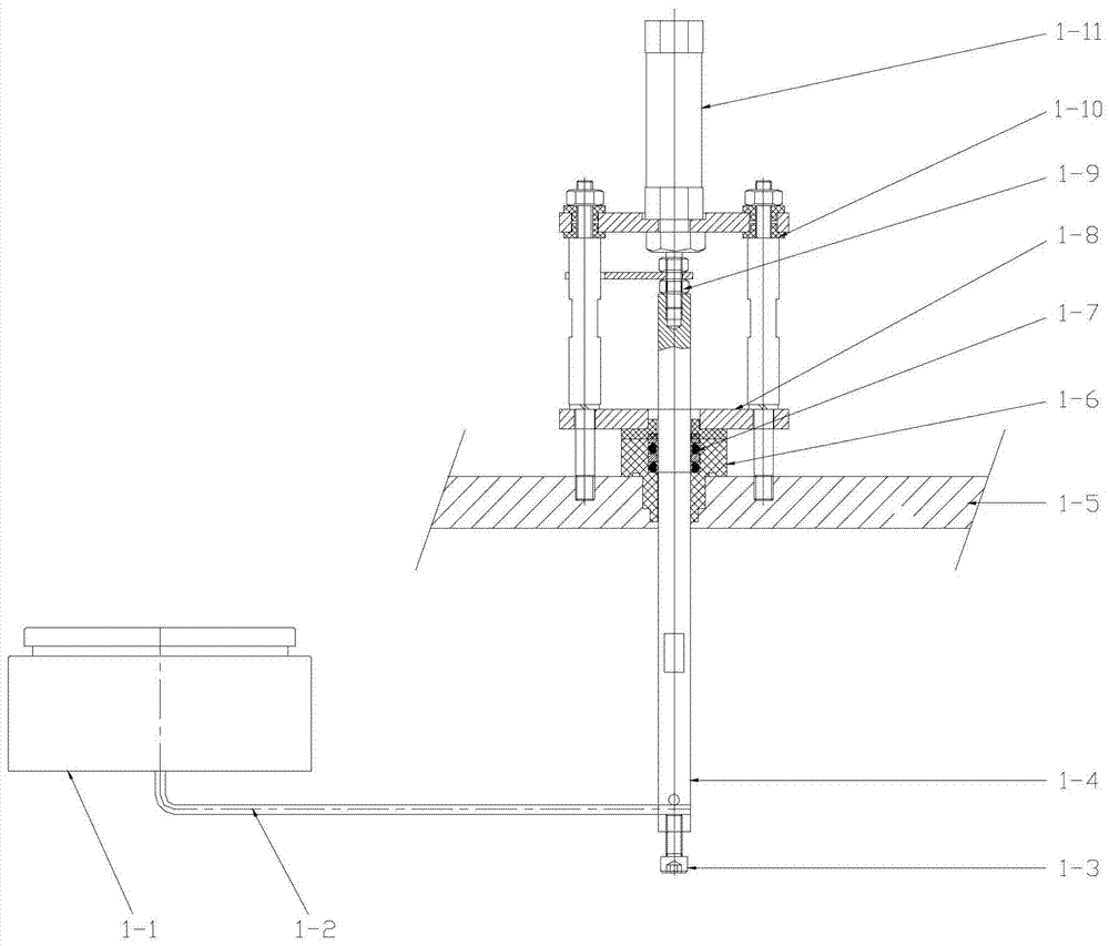
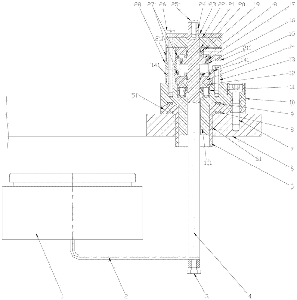
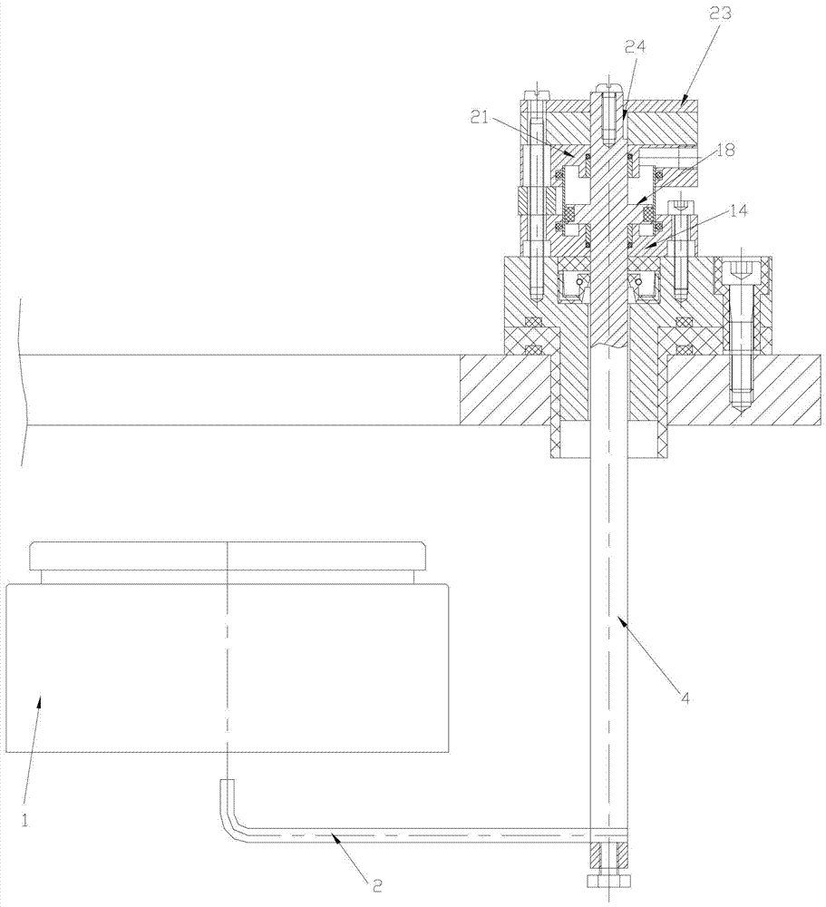
[0028] The pneumatic arc striking device of the vacuum cathode arc evaporation source of the preferred embodiment of the present invention, such as figure 2 , 3 , 4 referred to as arc ignition device includes arc ignition needle 2, piston rod 4, rigid arc ignition base 10, sealing insulation 5, dynamic seal 11, dynamic sealing pressure pad 12, piston assembly support, anti-rotation plate 23. The arc starter base 10 can also be made of other metal materials, such as copper and the like.

[0029] The piston rod 4 is integrally processed by the piston extension rod at the front end and the piston assembly at the rear end. In this way, it is possible to avoid the position deviation of the arc striking needle 2 or the increased distance between the arc striking needle 2 and the surface of the target block 1 due to the loose connection between the piston extension rod and the piston assembly in the prior art. The elbow cannot be in contact with the surface of the target block 1, ...


PUM


Abstract

A pneumatic arc ignition device for a vacuum cathode arc evaporation source, comprising an arc ignition needle, a piston extension rod, a piston assembly, a sealing insulator, a dynamic seal, a dynamic sealing pressure pad, and a support for the piston assembly. The dynamic sealing pressure pad is The supporting part of the piston assembly is pressed on the dynamic seal, and also includes a metal arc starter base, and the arc starter base is sleeved on the piston extension rod through the middle hole and connected to the arc evaporation source. The arc starter base is fixedly connected to the flange, the sealing insulating part is clamped between the arc starter base and the arc evaporation source connecting flange, and the bottom surface of the rear end of the arc starter base has a The protrusions between the extension rods are used to separate them, the piston assembly support is fixed on the front end face of the base of the arc starter, and the dynamic seal is embedded in the front end face of the base of the arc starter . The invention can reduce the rate of defective products and lower the production cost.

Description

technical field [0001] The invention relates to a pneumatic arc starting device for a vacuum cathode arc evaporation source. Background technique [0002] Vacuum cathodic arc deposition is one of the mainstream technologies for hard protective films for ion plating tools and decorations. The specific coating process is as follows: the vacuum cathode arc evaporation source is installed on the side wall of the vacuum coating chamber, the front end of the evaporation source penetrates into the vacuum coating chamber, and the coating material on it—the target block faces the workpiece to be plated in the vacuum coating chamber. The arc ignition device ignites a cluster of vacuum arc micro-arc spots on the surface of the target block. The high temperature and field effect in the arc spot area make the target vaporize to generate metal vapor, which is ionized into plasma and emitted into space, and deposited on the surface of the workpiece. film. [0003] The arc ignition device...

Claims


Application Information

Patent Timeline
Patent Type & Authority Patents(China)
IPC IPC(8): C23C14/32
Inventor 李志荣李志方罗志明李秋霞
Owner DONGGUAN HUICHENG VACUUM TECH
Why Eureka
Try Eureka