Check patentability & draft patents in minutes with Patsnap Eureka AI!

Comparator circuit

A technology of comparator circuits and resistors, which is applied in multiple input and output pulse circuits, electrical components, pulse processing, etc., can solve the problems of large influence and inapplicability of comparator circuits, etc., and achieve the effect of precise and adjustable flipping threshold

Pending Publication Date: 2018-03-06
SHANGHAI ORIENT CHIP TECH CO LTD
View PDF4 Cites 7 Cited by
  • Summary
  • Abstract
  • Description
  • Claims
  • Application Information

AI Technical Summary

Problems solved by technology

Of course, if the width-to-length ratios of the MOS transistor M10 and the MOS transistor M11 are different, voltage comparisons with different thresholds can also be realized, but this can only achieve one comparison threshold, and the threshold is greatly affected by the process.
Therefore, this comparator circuit cannot be used in systems that require precise control of the comparator threshold

Method used


Image

  • Comparator circuit
  • Comparator circuit
  • Comparator circuit

Examples


Embodiment Construction

[0032] Below in conjunction with the drawings, preferred embodiments of the present invention are given and described in detail.

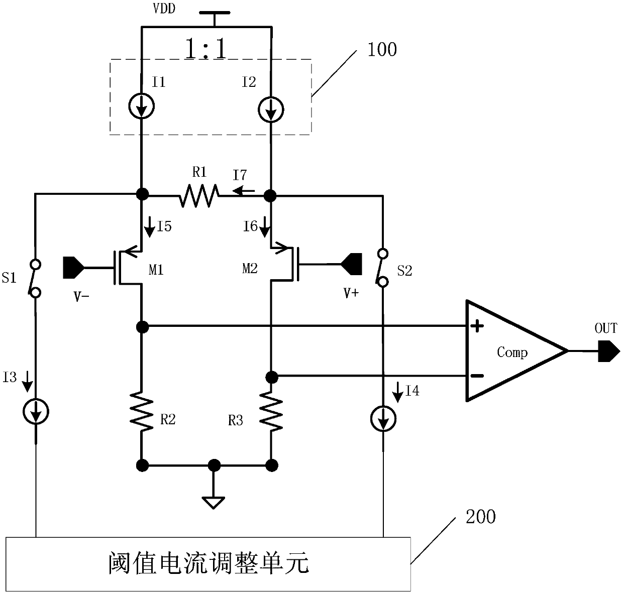
[0033] Such as figure 2 , 3 As shown, the present invention, that is, a comparator circuit, which includes:

[0034] A current mirror load 100, the first input end of which is connected to the second input end and receives the working voltage signal VDD, specifically, the current mirror load 100 includes: a first current source I1 and a second current source I2, the first current source I1 is connected to the input terminal of the second current source I2 and receives the working voltage signal VDD, wherein the currents of the first current source I1 and the second current source I2 are the same, that is, I1=I2;

[0035] The first MOS transistor M1, its gate receives the negative comparison voltage signal V-, its source is connected to the first output terminal of the current mirror load 100, that is, the output terminal of the first current sou...


PUM


Abstract

The invention relates to a comparator circuit. The comparator circuit comprises a current mirror load, a first MOS tube, a second MOS tube, a comparator unit, a first switch, a second switch, and a threshold current adjusting unit, wherein the source of the first MOS tube is connected with the first output end of the current mirror load, and the drain thereof is grounded through a second resistor;the source of the second MOS tube is connected with the second output end of the current mirror load and is connected with the source of the first MOS tube through a first resistor, and the drain thereof is grounded through a third resistor; one end of the first switch is connected with the source of the first MOS tube, and the other end thereof is connected with a first threshold current source;one end of the second switch is connected with the source of the second MOS tube, and the other end thereof is connected with the second threshold current source; and the threshold current adjustingunit is connected with the first threshold current source and the second threshold current source so as to adjust the current of each of the first threshold current source and the second threshold current source. The comparator circuit disclosed by the invention can realize the precise adjustable of a comparator overturn threshold by producing the voltage difference at the first MOS tube and the second MOS tube.

Description

technical field [0001] The present invention relates to a comparator circuit. Background technique [0002] As we all know, comparators are widely used in judging the size of various analog signals. Such as figure 1 As shown, the conventional comparator circuit is a zero-crossing comparator for judging the voltage at both ends, which includes a plurality of MOS transistors M8-M14, wherein the sources of the MOS transistor M8 and the MOS transistor M9 are connected, and the input voltage signal V+ , V- are directly added to the gates of MOS transistor M8 and MOS transistor M9 respectively, and the width-to-length ratios of MOS transistor M8 and MOS transistor M9, MOS transistor M10 and MOS transistor M11 are all equal, when the input voltage signal V+ is higher than the input voltage signal When V-, the current that the MOS transistor M9 pours into the gate of the MOS transistor M12 is smaller than the current pulled down by the MOS transistor M11, so that the gate voltage ...

Claims


Application Information

Patent Timeline
Patent Type & Authority Applications(China)
IPC IPC(8): H03K5/24
CPCH03K5/2472
Inventor 不公告发明人
Owner SHANGHAI ORIENT CHIP TECH CO LTD
Features
  • R&D
  • Intellectual Property
  • Life Sciences
  • Materials
  • Tech Scout
  • Unparalleled Data Quality
  • Higher Quality Content
  • 60% Fewer Hallucinations
Learn More