Phase locked loop with phase correction in the feedback loop

Active Publication Date: 2013-02-07
QUALCOMM INC
View PDF11 Cites 49 Cited by
  • Summary
  • Abstract
  • Description
  • Claims
  • Application Information

AI Technical Summary

Benefits of technology

[0008]The phase correction circuitry may correct the phase of the output of the fractional divider by delaying the phase of the output of the fractional divider so a phase difference between the referen

Problems solved by technology

The complexity of electronic devices has increased dramatically in the last

Method used


Image

  • Phase locked loop with phase correction in the feedback loop
  • Phase locked loop with phase correction in the feedback loop
  • Phase locked loop with phase correction in the feedback loop

Examples


Embodiment Construction

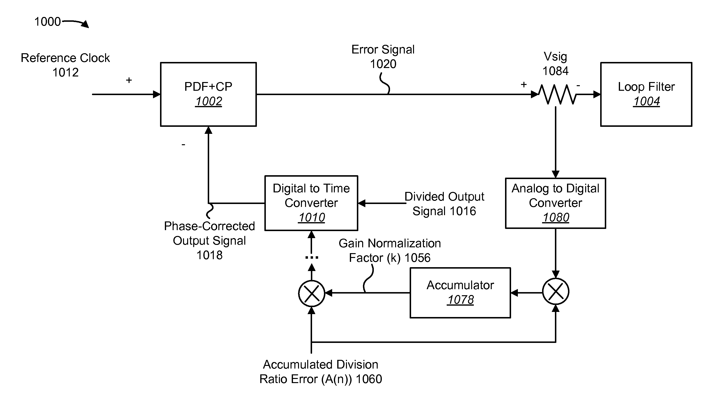
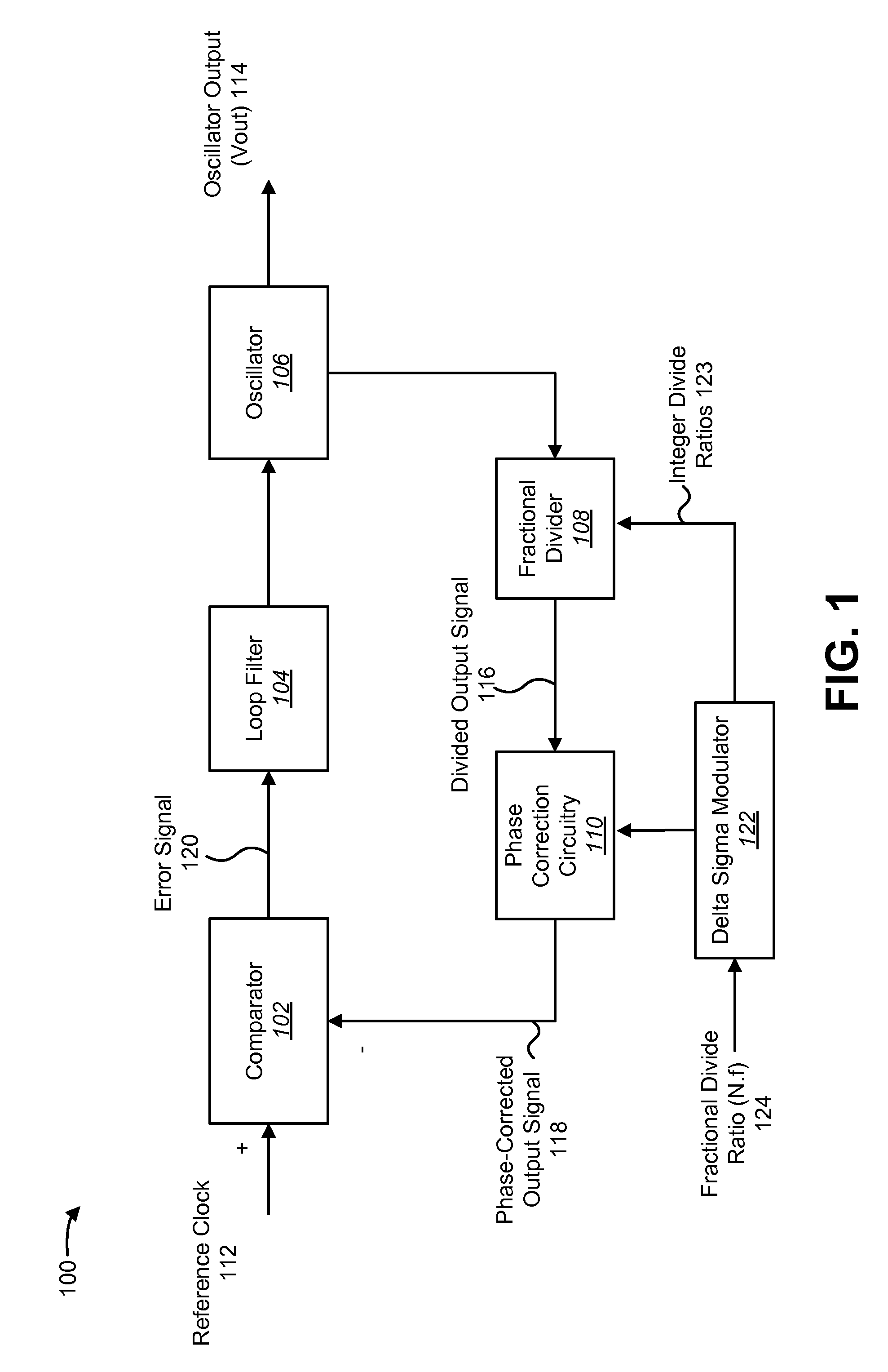
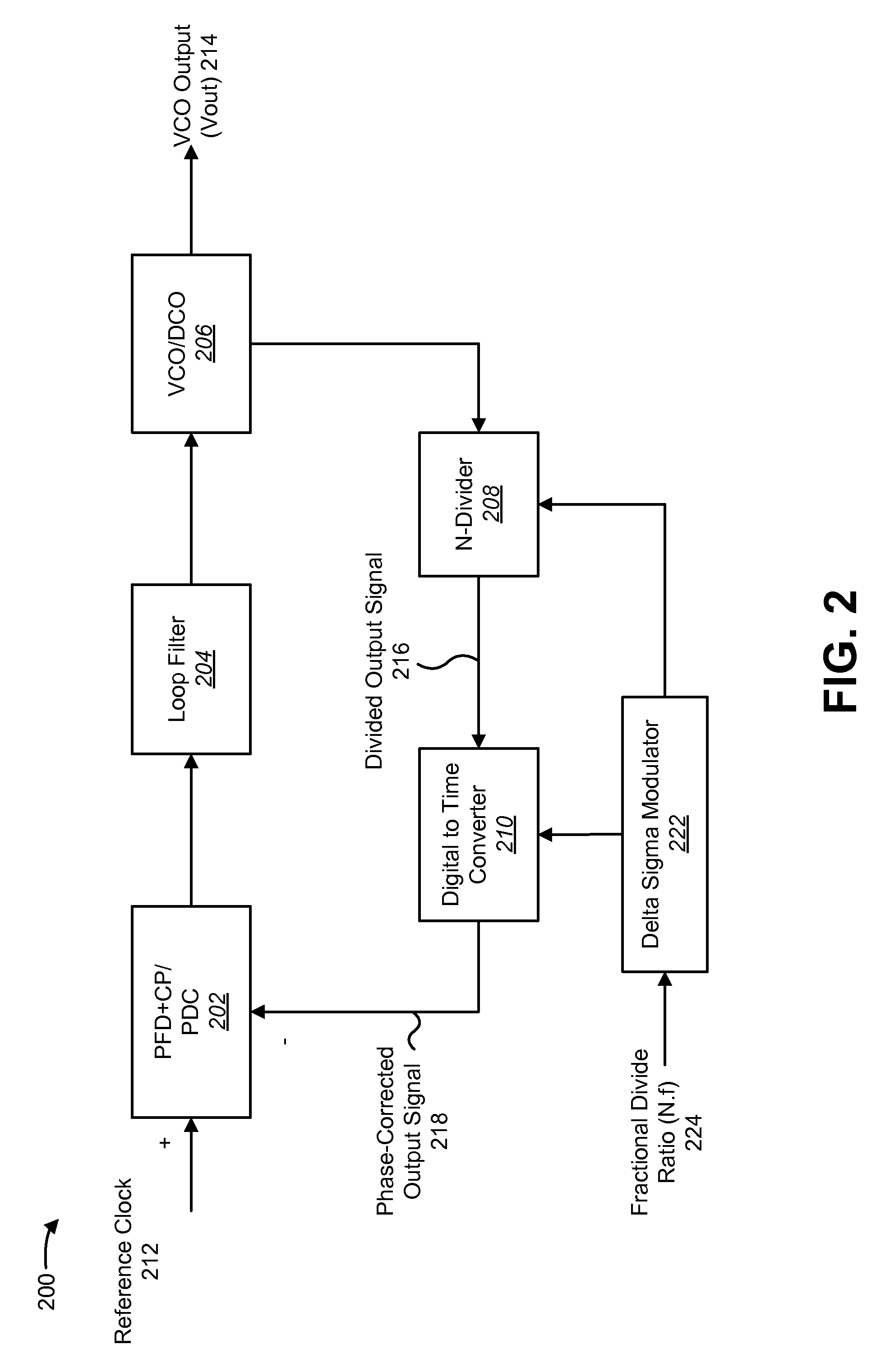
[0026]A phase locked loop (PLL) may be used to generate oscillating signals that are locked, relative to an input reference clock, in phase, frequency or both. An N-divider may be placed in a feedback path of a PLL to implement a frequency synthesizer that is capable of producing an output with a variety of frequencies. In some configurations, a PLL may use a fractional N-divider to enable finer tuning of the output frequency. Such fractional-N PLLs may use a delta sigma modulator (DSM) to determine instantaneous divide ratios used by the N-divider. The DSM, however, may cause noise at certain offsets from the carrier, i.e., the DSM may cause jitter in the phase of the feedback path signal. Furthermore, the DSM may cause spurs.

[0027]Therefore, the present systems and methods may use phase correction in the feedback loop of the PLL, e.g., a digital to time converter at the output of the N-divider. This may reduce delta-sigma noise at the input of a phase comparator circuit (e.g., pha...


PUM


Abstract

A frequency synthesizer circuit is disclosed. The frequency synthesizer circuit includes a comparator circuit coupled to a reference clock and a phase-corrected output signal. The frequency synthesizer circuit also includes a loop filter coupled to the comparator circuit. The frequency synthesizer circuit also includes an oscillator coupled to the loop filter. The frequency synthesizer circuit also includes a fractional divider coupled to an output of the oscillator. The frequency synthesizer circuit also includes phase correction circuitry that corrects a phase of an output of the fractional divider to produce the phase-corrected output signal.

Description

TECHNICAL FIELD[0001]The present disclosure relates generally to communication systems. More specifically, the present disclosure relates to a phase locked loop with phase correction in the feedback loop.BACKGROUND[0002]Electronic devices (cellular telephones, wireless modems, computers, digital music players, Global Positioning System units, Personal Digital Assistants, gaming devices, etc.) have become a part of everyday life. Small computing devices are now placed in everything from automobiles to housing locks. The complexity of electronic devices has increased dramatically in the last few years. For example, many electronic devices have one or more processors that help control the device, as well as a number of digital circuits to support the processor and other parts of the device.[0003]Wireless communication systems are widely deployed to provide various types of communication content such as voice, video, data and so on. These systems may be multiple-access systems capable o...

Claims


Application Information

Patent Timeline
IPC IPC(8): H03L7/08
CPCH03L7/1976
Inventor ZHANG, GANG
Owner QUALCOMM INC
Why Eureka
Try Eureka