Electronic fault detection unit

a fault detection and electronic technology, applied in error detection/correction, redundant hardware error correction, instruments, etc., can solve the problems of requiring resource use, difficult monitoring of hard real-time constraints, and complex reciprocal checking in softwar

Active Publication Date: 2016-03-31
NXP USA INC
View PDF5 Cites 49 Cited by
  • Summary
  • Abstract
  • Description
  • Claims
  • Application Information

AI Technical Summary

Problems solved by technology

Doing the reciprocal checking in software is quite complex.
Also, monitoring the hard real-time constraints is difficult as software runs in a virtual time.
The waiting may use semaphores which are another potential source of dead-lock.
All this adds complexity and requires resources to be used.

Method used


Image

  • Electronic fault detection unit
  • Electronic fault detection unit
  • Electronic fault detection unit

Examples


Embodiment Construction

[0048]In the following, for sake of understanding, the circuitry is described in operation. However, it will be apparent that the respective elements are arranged to perform the functions being described as performed by them.

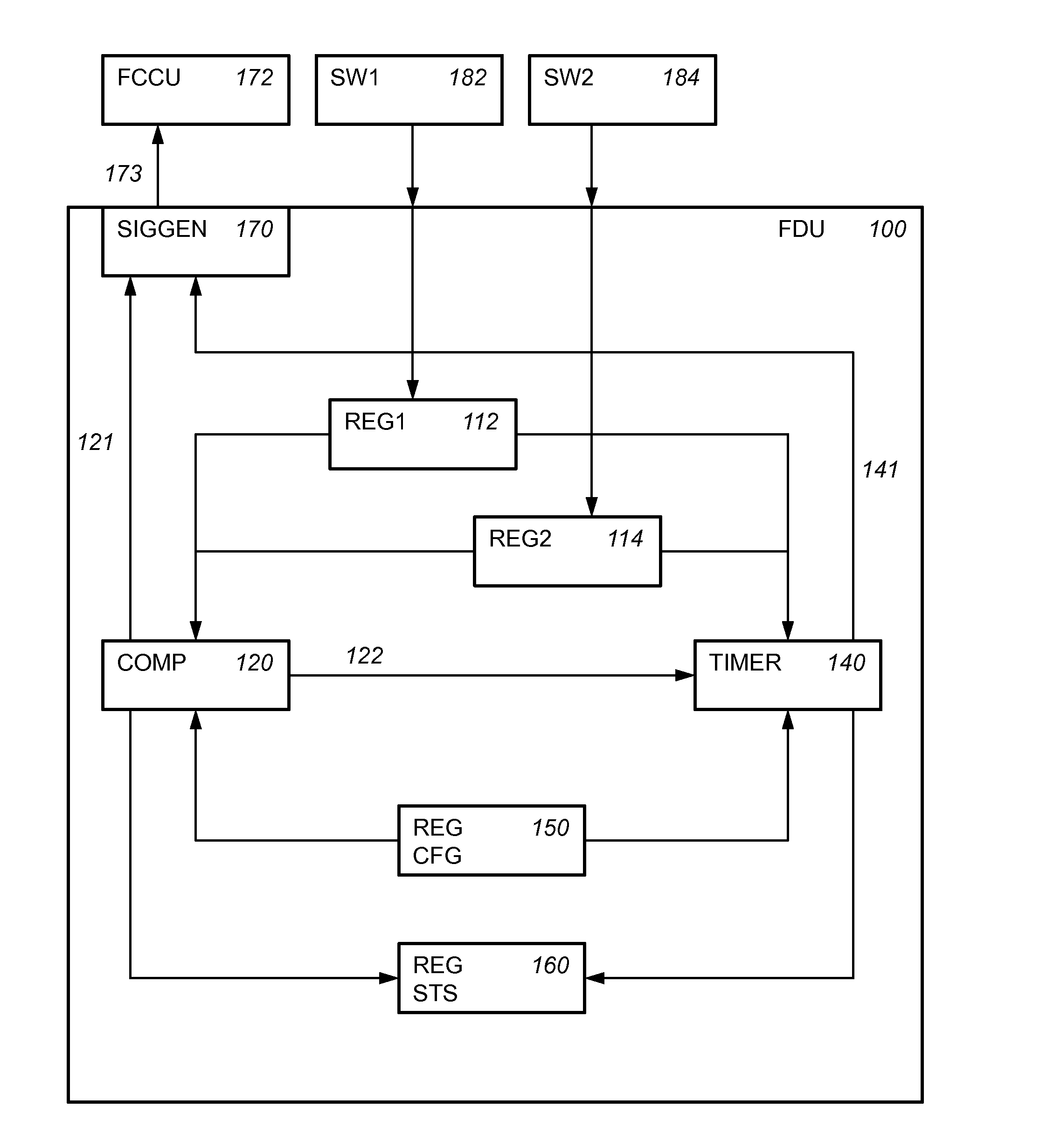
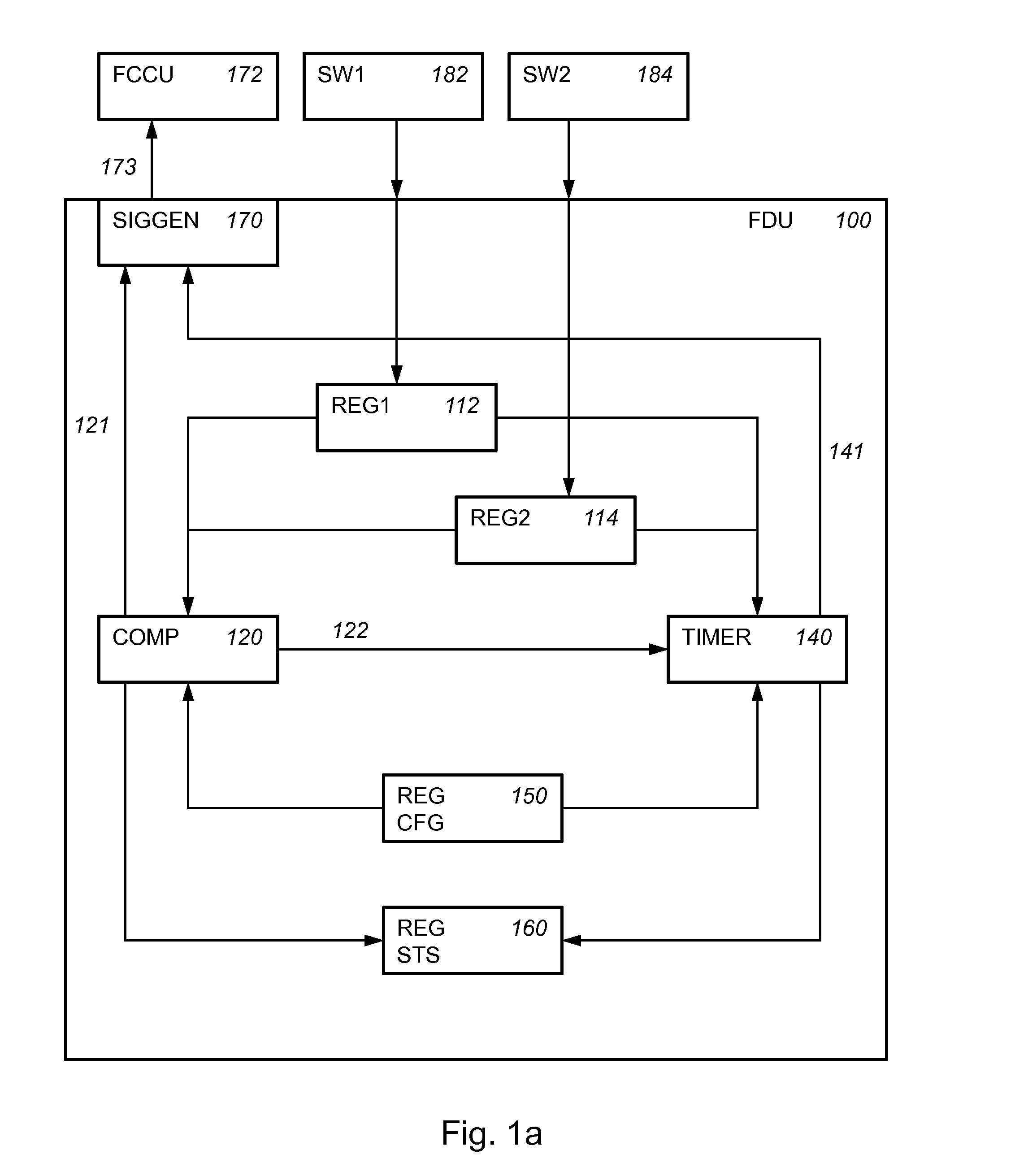
[0049]FIG. 1a schematically shows an example of an embodiment of a fault detection unit 100.

[0050]Fault detection unit 100 comprises a first register (REG1) 112 and a second register (REG2) 114. First register 112 is arranged to be written from a first software portion (SW1) 182, and second register 114 is arranged to be written from a second software portion (SW2) 184.

[0051]For example, first software portion 182 may be arranged to write first data to first register 112; and second software portion 184 may be arranged to write second data to second register 114. Fault detection unit 100 may be applied to a first and second software portion, e.g., that need to monitor each other. For example, such a situation is present in many safety or fault tolerant applicati...


PUM


Abstract

An electronic fault detection unit is provided that has a first register, a second register, a comparator circuit, and a timer circuit. The first and second register can be written from a first software portion, and a second software portion, respectively. The comparator circuit is arranged to detect that both the first and second register have been written, verify a relationship between first data written to the first register and second data written to the second register, and signal a fault upon said verification failing. The timer circuit is arranged to signal a fault if said verification of the comparator circuit does not occur within a time limit.

Description

FIELD OF THE INVENTION[0001]This invention relates to an electronic fault detection unit, a data processing device, an integrated circuit, an electronic fault detection method, and a non-transitory tangible computer readable storage medium.BACKGROUND OF THE INVENTION[0002]For safety or security relevant applications, etc., fault tolerance is important. In part, fault tolerance may be obtained by detecting faults in hardware and / or software. When a fault has been detected some appropriate response can be taken.[0003]It is known in the art to use two almost identical central processing units (CPUs), one of which operates as the master CPU and the other as the “checker” CPU. Both central processing units execute basically the same program code and receive the same input data. The outputs of the two central processing units are compared to each other in order to identify errors of the master CPU during operation. Doing the reciprocal checking in software is quite complex. Also, monitori...

Claims


Application Information

Patent Timeline
Patent Type & Authority Applications(United States)
IPC IPC(8): G06F11/16
CPCG06F2201/82G06F11/1616G06F11/1641G06F11/0721G06F11/0757G06F11/1497G06F11/1645
Inventor BACA, DAVID
Owner NXP USA INC
Why Eureka
Try Eureka