Unlock instant, AI-driven research and patent intelligence for your innovation.

Punch assembly with replaceable punch tip secured by coupling pin

A technology for connecting pins and punches, applied in the fields of punch tool assemblies and metal processing punch assemblies, can solve problems such as punch tip wear

Inactive Publication Date: 2018-03-06
MATE PRECISION TOOLING
View PDF13 Cites 0 Cited by
  • Summary
  • Abstract
  • Description
  • Claims
  • Application Information

AI Technical Summary

Problems solved by technology

As a result, punch tips may become worn and need to be sharpened or replaced

Method used


Image

  • Punch assembly with replaceable punch tip secured by coupling pin
  • Punch assembly with replaceable punch tip secured by coupling pin
  • Punch assembly with replaceable punch tip secured by coupling pin

Examples


Embodiment Construction

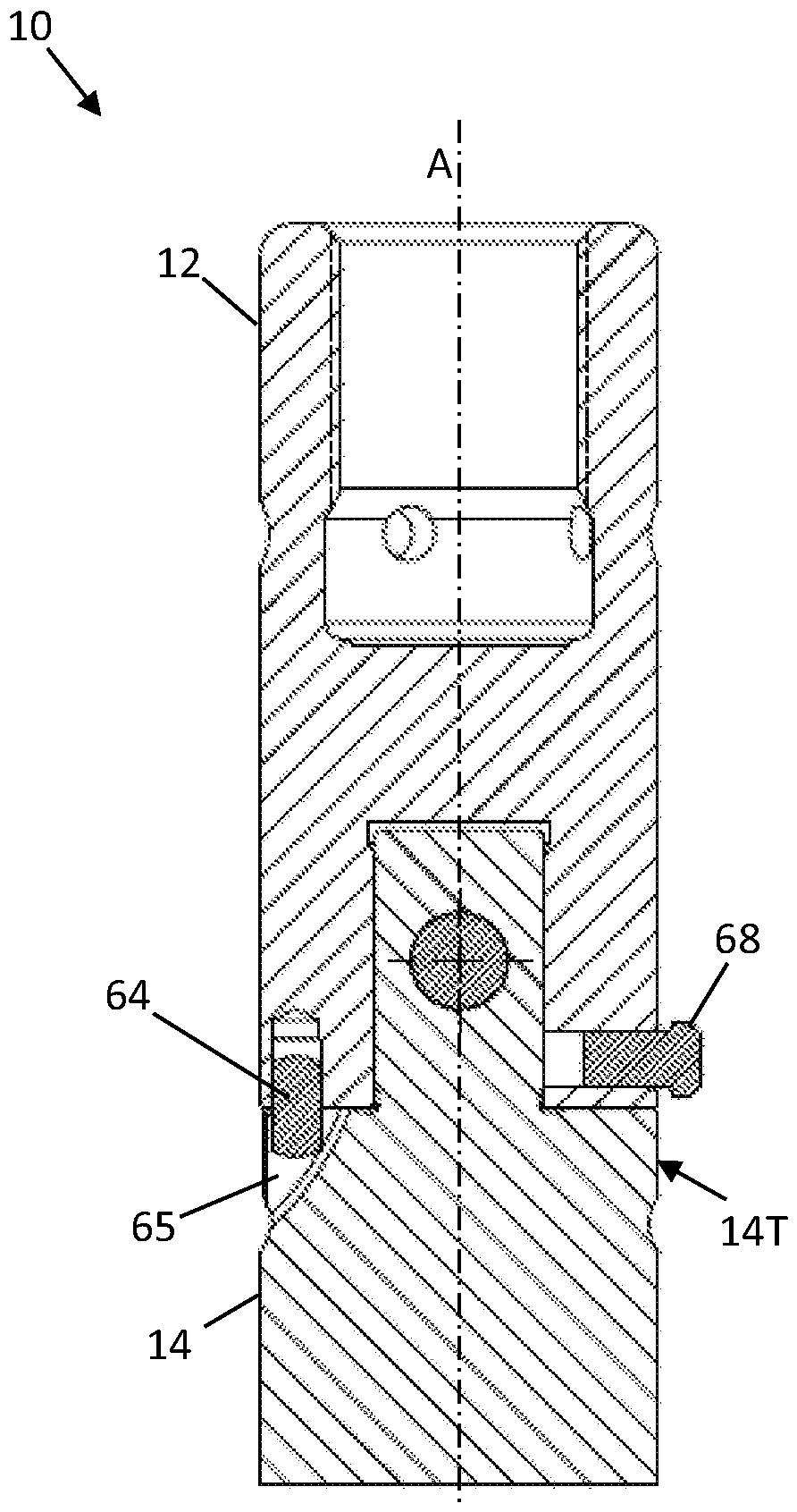
[0035] figure 1 is a cross-sectional view of a punch assembly 10 having a punch body 12 and a replaceable punch tip 14 terminating in a punch tip 15 . In this particular example, the punch assembly 10 is disposed within a bushing or punch guide 16 that is mounted in an upper turret 18 of a punch apparatus 20 .

[0036] The punching apparatus 20 includes an upper turret 18 and a lower turret 22 . A die 24 is mounted in a lower turret 22 opposite the punch tip 14 on the other side of a workpiece 25 (eg, a sheet metal part or other material to be machined).

[0037] In operation of the punch assembly (or punch) 10, the punch tip 15 of the punch tip 14 is driven through an aperture in the stripper 26 on the bottom surface of the punch guide 16, extending through the workpiece 25 and into the die 24. The punch tip 15 separates the residual material from the workpiece 25 during the stamping process, and the residual material is accommodated in the die 24 . The stripper 26 rests ...


PUM


Abstract

A punch assembly (10) includes a punch body (12) having an axis and a replaceable punch tip (14) configured for a punching operation, e.g., in a punch press apparatus. A laterally manipulated couplingpin (42) is provided to selectively engage the punch tip (14) with the punch body (12) along the axis, and to selective disengage the punch tip (14) from the punch body (12).

Description

technical field [0001] The present disclosure relates generally to machine tools, and in particular to punch assemblies for metalworking. In particular, the present disclosure relates to punch tool assemblies suitable for use in punch machines, including but not limited to high speed punches used in manufacturing and production. Background technique [0002] Industrial processing machinery, including rotary and orbital punch presses, is widely used to manufacture sheet metal workpieces and other sheet components (eg, metal, plastic, leather, etc.). Automated punching presses are commonly used in production applications and include single and multi-station presses, plate brakes, plate and coil feeding systems, orbital machine tool systems, and other manufacturing equipment suitable for pressing, bending and stamped sheet metal components for the manufacture of sheet metal and other workpieces into a multitude of useful products. [0003] In particular punch presses have fou...

Claims


Application Information

Patent Timeline
Patent Type & Authority Applications(China)
IPC IPC(8): B21D28/34B21D37/14B26D7/26B26F1/14
CPCB21D28/34B21D37/14B26D7/2614B26F1/14B30B15/065
Inventor B.蒂尔格斯
Owner MATE PRECISION TOOLING