Method for automatically adjusting powder supplying amount of metal 3D printing machine

A 3D printer, automatic adjustment technology, applied in the direction of improvement of process efficiency, additive manufacturing, additive processing, etc., can solve the problems of insufficient powder supply and large volume of residual materials, etc.

Active Publication Date: 2018-03-09
BEIJING E PLUS 3D TECH CO LTD
View PDF8 Cites 12 Cited by
  • Summary
  • Abstract
  • Description
  • Claims
  • Application Information

AI Technical Summary

Problems solved by technology

Although this form of quantitative powder supply can prevent the remaining material from entering the powder supply tank directly, and can also improve the utilization rate of powder to a certain extent, however, according to the above-mentioned 3D printing principle description, it can be known that when parts are stacked and formed layer by layer, each The contours and shapes of one layer are all different, but the powder conveyed by the powder spreading body is quantitative, which will inevitably cause insufficient powder supply on the layer with a larger effective physical area, and some layers with a smaller effective physical area The amount of powder supplied exceeds the actual amount, resulting in a large volume of remaining material

Method used


Image

  • Method for automatically adjusting powder supplying amount of metal 3D printing machine
  • Method for automatically adjusting powder supplying amount of metal 3D printing machine
  • Method for automatically adjusting powder supplying amount of metal 3D printing machine

Examples


Embodiment 1

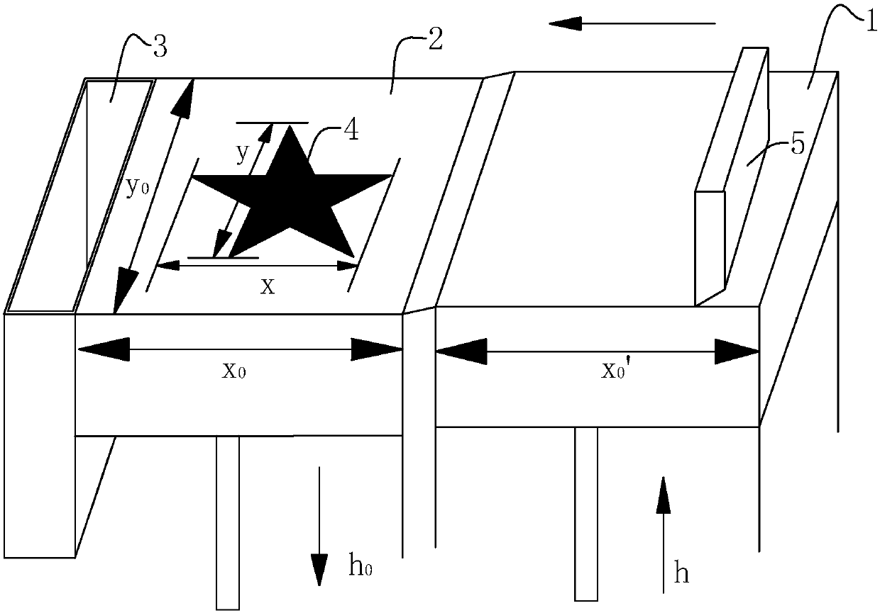
[0079] first according to Figures 1 to 3 The 3D printing process and the derivation process of the powder supply height calculation formula are described.

[0080] Such as figure 1 As shown in , the forming platform of the 3D printing equipment includes a powder supply cylinder 1, a forming cylinder 2, a residual material collection box 3, and a powder spreading scraper 5 for feeding and spreading powder. During printing, the powder supply cylinder 1 rises for a distance of h to supply powder, and the forming cylinder 2 descends for a thickness h of the current printing layer 0 , the powder spreading scraper 5 pushes the powder with a thickness of the actual powder supply height h to the molding cylinder 2 along the direction from the powder supply cylinder 1 to the residual material collection box 3, and the powder passing through the part 4 forms a metal entity, and the residual material is continuously moved The powder spreading scraper 5 is pushed into the surplus mater...

Embodiment 2

[0103] Such as Figure 5 Shown in, its difference with embodiment 1 is: in steps S1 and S3, increase read parameter x0 and x, and with reference to formula (3): Calculate the optimum toner supply height h of the current printing layer.

[0104] It should be pointed out that no matter it is embodiment 1 or 2, only the influence of the contour shape of the part 4 during the printing process on the toner supply height is considered, but, in actual printing, the operator's operation during the printing process and during the printing process The previous treatment of the powder in the powder supply tank 1 (for example, whether it is dried or not) will affect the value of the powder supply height h to a certain extent. Therefore, before the calculation formula is multiplied by a correction factor A, its value should be 0.9 To 1.5, to adapt to the current operation and further adjust the powder supply height h value.

[0105] During the 3D printing process, the amount of remainin...


PUM

PropertyMeasurementUnit
correction factoraaaaaaaaaa

Abstract

The invention discloses a formula for automatically adjusting the powder supplying height of a metal 3D printing machine. The formula includes the following steps that S1, the size parameters x0 and y0 of a forming cylinder and the size parameter x0' of a powder supplying cylinder are input; S2, the values of x and y are obtained and input according to the contour of a current printing layer; S3,the layer thickness h0 of the current printing layer is obtained; S4, the powder supplying height is changed in real time according to the formula (please see the formula in the specifications); and S5, when the S1, the S2, the S3 and the S4 are conducted for the fifteenth time, the coefficient A is multiplied before the current powder supplying height calculating formula according to the waste material amount in a waste material collecting box, the value ranges from 0.9 to 1.5, and the powder supplying height is increased or reduced according to the waste material amount. The powder supplyingheight of the current printing layer can be dynamically adjusted in real time according to the part section area, the part placing position, the powder batch, the powder density changes in the forming cylinder and the powder supplying cylinder and changes of operators and other factors, and therefore the size of waste materials can be minimized on the premise that powder is fully spread on the current printing layer.

Description

technical field [0001] The invention relates to a method for calculating the powder supply amount of a 3D printer, in particular to a method for automatically adjusting the powder supply amount of a metal 3D printer. Background technique [0002] Selected area laser melting technology, also known as metal 3D printing technology, its working principle is as follows: figure 1 As shown in , first, use the existing slicing and laser scanning path planning software to design the path of the laser beam; then, the powder supply cylinder rises to a certain height, the forming cylinder descends to a height of layer thickness, and the powder spreading scraper will supply the powder The powder on the cylinder that is higher than the forming cylinder is pushed to the surface of the forming cylinder, and spread evenly, and the excess material is pushed to the remaining material collection box at the other end, and then the machine drives the laser beam to process the evenly spread powder...

Claims


Application Information

Patent Timeline
Patent Type & Authority Applications(China)
IPC IPC(8): B22F3/105B33Y50/02B33Y30/00
CPCB22F3/003B33Y30/00B33Y50/02B22F10/00B22F10/28B22F12/67Y02P10/25
Inventor 郭东海吴朋越冯涛包洪彬李豫张国庆
Owner BEIJING E PLUS 3D TECH CO LTD
Why Eureka
Try Eureka