
Lathe clamping tool applicable to irregular slender axial spare parts

A technology for clamping tooling and slender shafts, which is applied to metal processing machinery parts, clamping, positioning devices, etc., can solve the problems of unstable clamping and bending of shaft parts, and achieve high clamping stability and clamping The effect of high reliability

Pending Publication Date: 2018-03-09
NANJING CHERVON AUTOMOBILE PRECISION TECH CO LTD
View PDF0 Cites 0 Cited by
  • Summary
  • Abstract
  • Description
  • Claims
  • Application Information

AI Technical Summary

Problems solved by technology

[0003] When the traditional CNC lathe clamps the slender shaft parts, it is easy to cause the bending of the shaft parts and the clamping is unstable

Method used


Image

  • Lathe clamping tool applicable to irregular slender axial spare parts
  • Lathe clamping tool applicable to irregular slender axial spare parts
  • Lathe clamping tool applicable to irregular slender axial spare parts

Examples


Embodiment Construction

[0014] The present invention will be specifically introduced below in conjunction with the accompanying drawings and specific embodiments.

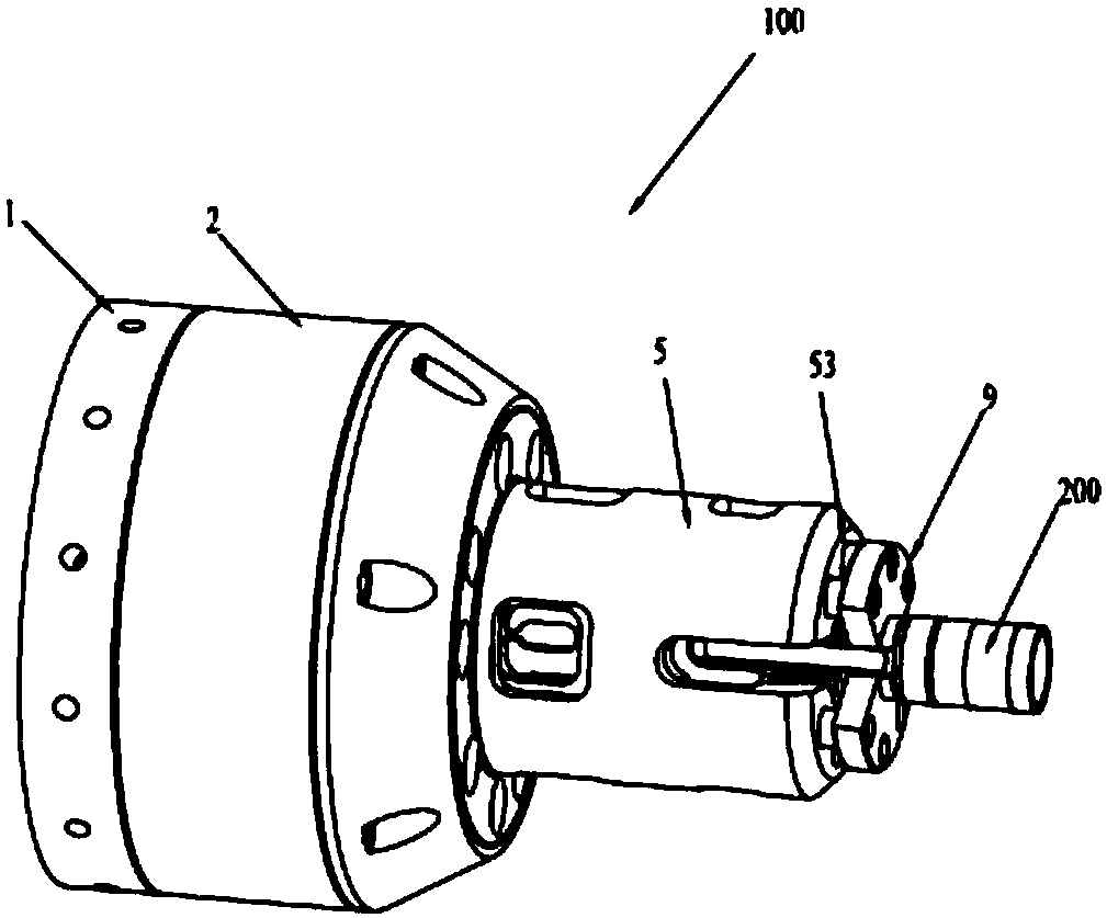
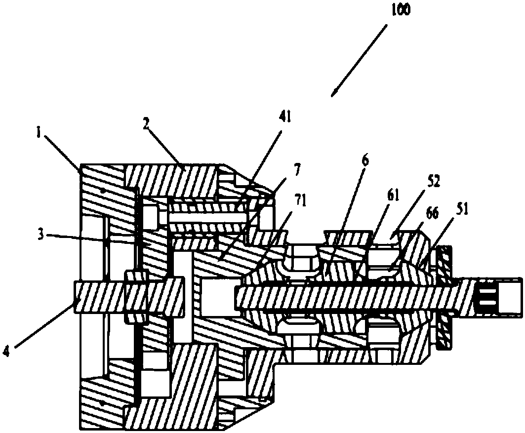
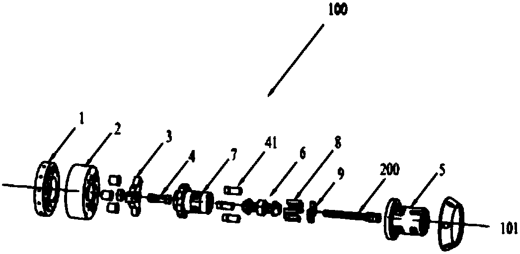
[0015] Such as Figure 1 to Figure 4 As shown, a lathe clamping tool 100 suitable for special-shaped slender shaft parts 200 includes: lathe connection plate 1, lathe rotary body 2 defining a rotary axis 101, lathe pull plate 3, pull plate fixing bolts 4, Driven pull rod 41 , clamping outer sleeve 5 , clamping inner sleeve 6 , bottom positioning sleeve 7 , positioning column 8 and axial positioning member 9 .

[0016] The lathe rotary body 2 is connected to the lathe connection plate 1; the lathe rotary body 2 rotates around the rotary axis 101; the lathe pull plate 3 is fixed to one end of the lathe pull rod by the pull plate fixing bolt 4; one end of the driven pull rod 41 is fixed to the lathe pull plate 3 The other end of the driven pull rod 41 is fixed to the clamping jacket 5; the lathe pull rod drives the clamping jacket 5 to slid...


PUM


Abstract

The invention discloses a lathe clamping tool applicable to irregular slender axial spare parts. A penetrating hole for inserting the irregular slender axial spare parts is formed at an inner clampingsleeve; the penetrating hole crosses through the inner clamping sleeve along a revolving axial line; both ends of the inner clamping sleeve along the direction of the revolving axial line is formed with a first clamping pawl and a second clamping pawl for clamping the irregular slender axial spare parts; the periphery of the first clamping pawl is formed with a first clamping oblique face; the periphery of the second clamping pawl is formed with a second clamping oblique face; one end of an outer clamping sleeve far from a driven pull rod is formed with a first force applying oblique face matched with the first clamping oblique face; one end of a bottom positioning sleeve contacts with a lathe revolving body; the bottom positioning sleeve is formed with a second force applying oblique face bottom positioning sleeve matched with the second force applying oblique face, and the second force applying oblique face bottom positioning sleeve is sleeved at the periphery of the inner clampingsleeve; the outer clamping sleeve is sleeved at the periphery of the bottom positioning sleeve. The lathe clamping tool applicable to irregular slender axial spare parts can achieve automatic clampingand high clamping stability.

Description

technical field [0001] The invention relates to a lathe clamping tool suitable for special-shaped slender shaft parts. Background technique [0002] The clamping mechanism usually used in traditional CNC lathe parts is a three-jaw clamping mechanism. The lathe pull rod of the lathe drives the three-jaw clamping mechanism to clamp the parts. [0003] When the traditional CNC lathe clamps the slender shaft parts, it is easy to cause the bending of the shaft parts and the clamping is unstable. Contents of the invention [0004] In order to solve the deficiencies of the prior art, the purpose of the present invention is to provide a lathe clamping tool suitable for special-shaped slender shaft parts, which can realize automatic clamping and has high clamping stability. [0005] A lathe clamping tool suitable for special-shaped slender shaft parts, which is characterized in that it includes: a lathe connecting plate, a lathe rotary body defining a rotary axis, a lathe pull pl...

Claims


Application Information

Patent Timeline
IPC IPC(8): B23Q3/12
CPCB23Q3/12
Inventor 张超李岩邓凌曲
Owner NANJING CHERVON AUTOMOBILE PRECISION TECH CO LTD
Features
  • Generate Ideas
  • Intellectual Property
  • Life Sciences
  • Materials
  • Tech Scout
  • Unparalleled Data Quality
  • Higher Quality Content
  • 60% Fewer Hallucinations
Learn More