Pneumatic clamping device

A clamping device, pneumatic technology, applied in the field of machining, can solve the problems of low degree of automation, different clamping force, poor stability, etc., to achieve the effect of high degree of automation, the same clamping force and good reliability

Active Publication Date: 2017-06-06
盐城捷恒仓储有限公司
View PDF6 Cites 11 Cited by
  • Summary
  • Abstract
  • Description
  • Claims
  • Application Information

AI Technical Summary

Problems solved by technology

At present, the common clamping devices are generally clamped manually, the degree of automation is low, and the clamping force is different each time, and the stability is poor.

Method used


Image

  • Pneumatic clamping device

Examples


Embodiment Construction

[0012] The present invention will be further described in detail below in conjunction with the accompanying drawings and examples. The following examples are explanations of the present invention and the present invention is not limited to the following examples.

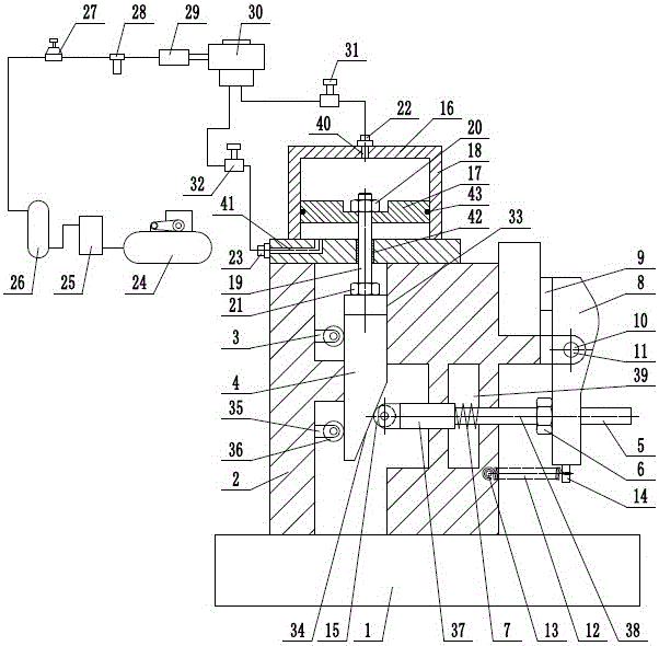
[0013] Such as figure 1 As shown, a pneumatic clamping device includes a base 1, a frame 2, a wedge guide assembly 3, a wedge 4, a slide rod 5, a slide rod adjustment nut 6, a compression spring 7, a pressure plate 8, and a pressure block 9 , Support pin 10, support lug 11, return tension spring 12, left tension spring column 13, right tension spring column 14, support roller 15, pneumatic cylinder 16, piston 17, cylinder support seat 18, connecting rod 19 , upper nut 20, lower nut 21, upper valve port 22, lower valve port 23, air compressor 24, aftercooler 25, gas storage tank 26, pressure control valve 27, lubricator 28, logic element 29, direction control Valve 30, upper flow control valve 31, lower flow control...


PUM


Abstract

The invention provides a pneumatic clamping device, and belongs to the technical field of mechanical processing. The pneumatic clamping device comprises a wedge block, a piston, and a connecting rod, wherein the wedge block is arranged on a wedge block chute by sliding up and down; a guide roller of a wedge block guide component is rotationally arranged on a guide supporting seat; a supporting roller is always matched with a sloping bench of the wedge block under the action of a compression spring; a threaded section of the right end of a sliding rod is in threaded connection with the lower end of a press plate; the piston is arranged in a pneumatic cylinder body by sliding up and down; the connecting rod is arranged on a cylinder body supporting seat by sliding up and down; an air compressor is connected with a rear cooler, a gas tank, a pressure control valve, an atomized lubricator, a logic element, and a direction control valve sequentially; and the other two ends of the direction control valve are connected with an upper valve port and a lower valve port through an upper flow control valve and a lower flow control valve respectively. The pneumatic clamping device provided by the invention automatically realizes clamping and releasing of a workpiece, and is reasonable in structure, high in degree of automation, same in clamping force each time, good in reliability and improved in clamping stability.

Description

technical field [0001] The invention relates to the technical field of machining, in particular to a pneumatic clamping device. Background technique [0002] Machining refers to the process of changing the shape or performance of a workpiece through a mechanical device. According to the difference in processing method, it can be divided into cutting processing and pressure processing. Turning, milling, planing and grinding are the four basic processing methods of mechanical processing. They are a more important part of parts processing. They mainly complete the processing of parts so that they can be used for the assembly of machinery and equipment. Including turning, milling, planing, and grinding. Different parts require different processing methods. For example, shaft parts generally only need turning, but some parts need to use two or more of them. The processing of parts can be completed. No matter in any kind of mechanical processing, fixtures are needed. Fixtures a...

Claims


Application Information

Patent Timeline
Patent Type & Authority Applications(China)
IPC IPC(8): B23Q3/08
CPCB23Q3/08
Inventor 周顺尧
Owner 盐城捷恒仓储有限公司
Why Eureka
Try Eureka