Clamping mechanism for grinding and polishing robot system for high-temperature alloy mechanical parts of engine

A robotic system and superalloy technology, which is used in grinding machine parts, grinding/polishing equipment, grinding machines, etc., to solve problems such as insufficient support force, easy slippage during grinding and polishing, and damage to engine alloy components.

Inactive Publication Date: 2019-09-27
NANJING YUSHENG ROBOT CO LTD
View PDF9 Cites 11 Cited by
  • Summary
  • Abstract
  • Description
  • Claims
  • Application Information

AI Technical Summary

Problems solved by technology

[0002] In the prior art, the engine alloy mechanism parts need to be ground and polished by the grinding and polishing robot system for later use. Since the engine alloy mechanism parts are irregular structural parts, the existing clamping mechanism is clamping and penetrating. If the clamping force is too large, it may cause damage to the engine alloy mechanism. If the clamping force is insufficient, slippage will easily occur during the grinding and polishing process, which will affect the grinding and polishing operation, which is very inconvenient, so here is a design. Clamping mechanism for the grinding and polishing robot system of high-temperature alloy mechanism parts of the engine, in order to solve the above problems

Method used


Image

  • Clamping mechanism for grinding and polishing robot system for high-temperature alloy mechanical parts of engine
  • Clamping mechanism for grinding and polishing robot system for high-temperature alloy mechanical parts of engine
  • Clamping mechanism for grinding and polishing robot system for high-temperature alloy mechanical parts of engine

Examples


Embodiment Construction

[0026] The embodiment of the present application solves the problems raised in the prior art by providing a clamping mechanism for the grinding and polishing robot system of the superalloy mechanism of the engine; the following will be clearly and completely described in conjunction with the technical solution in the embodiment of the present invention, Apparently, the described embodiments are only some of the embodiments of the present invention, but not all of them. Based on the embodiments of the present invention, all other embodiments obtained by persons of ordinary skill in the art without making creative efforts belong to the protection scope of the present invention.

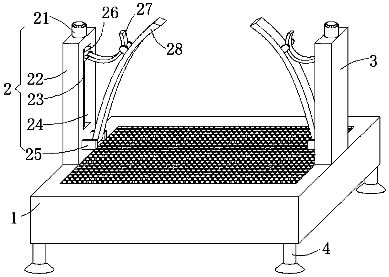
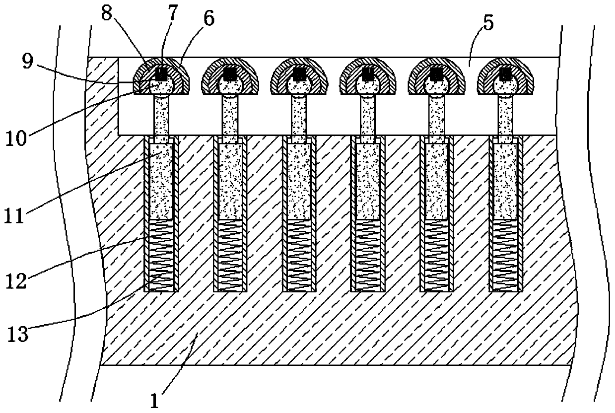
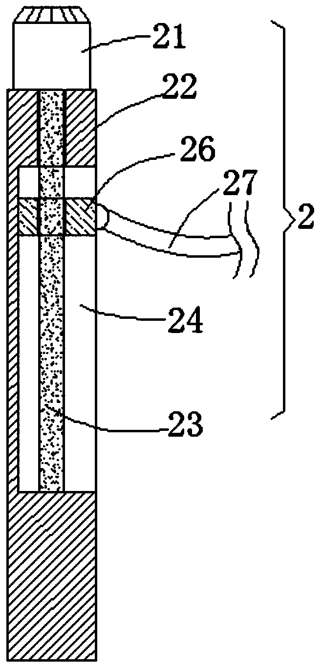
[0027] see Figure 1-4 , this embodiment provides a clamping mechanism for a grinding and polishing robot system for high-temperature alloy parts of an engine, including a workbench 1 and a data processing module 15 embedded in the inner cavity of the workbench 1, and the left and right sides of the top...


PUM


Abstract

The invention discloses a clamping mechanism for a grinding and polishing robot system for high-temperature alloy mechanical parts of an engine. The clamping mechanism comprises a workbench and a data processing module, wherein the data processing module is embedded in an inner chamber of the workbench. A first supporting mechanism and a second supporting mechanism are vertically arranged at the middle segment positions of the left side and the right side of the top end face of the workbench respectively. The first supporting mechanism and the second supporting mechanism both comprise supporting columns, and servo motors are fixedly arranged on the top end faces of the two supporting columns. The two servo motors are connected with threaded rods respectively through power shafts, the outer walls of the two threaded rods are rotationally sleeved with lifting sliding blocks through external threads, and the lifting sliding blocks are respectively positioned in inner chambers of two rectangular lifting grooves. The positions, being 1 / 4 of the distance from the top end, of the outer walls of two arc-shaped clamping blocks are respectively hinged with the side walls at quarter of the tip ends of two hinged plates, and pressure sensors are embedded in the top ends of the opposite side walls of the two arc-shaped clamping blocks. The clamping mechanism is convenient to quickly clamp the parts to be ground and polished, can ensure the good clamping stability, can also ensure no slippage in the grinding and polishing process, and improves the grinding and polishing precision.

Description

technical field [0001] The invention relates to the related technical field of the clamping mechanism of the grinding and polishing robot system, in particular to a clamping mechanism for the grinding and polishing robot system of the superalloy engine parts. Background technique [0002] In the prior art, the engine alloy mechanism parts need to be ground and polished by the grinding and polishing robot system for later use. Since the engine alloy mechanism parts are irregular structural parts, the existing clamping mechanism is clamping and penetrating. If the clamping force is too large, it may cause damage to the engine alloy mechanism. If the clamping force is insufficient, slippage will easily occur during the grinding and polishing process, which will affect the grinding and polishing operation, which is very inconvenient, so here is a design. The clamping mechanism used in the grinding and polishing robot system of high-temperature alloy mechanism parts of the engine...

Claims


Application Information

Patent Timeline
Patent Type & Authority Applications(China)
IPC IPC(8): B24B19/00B24B41/06B24B49/16B24B47/04
CPCB24B19/00B24B41/06B24B47/04B24B49/16
Inventor 李雲孙玲曹丹峰
Owner NANJING YUSHENG ROBOT CO LTD
Why Eureka
Try Eureka