Tool clamp

A technology of tooling fixtures and sliding seats, which is applied in the field of tooling fixtures, can solve the problems of inconvenient use, low clamping stability, inconvenient construction or inspection of the bottom surface of workpieces, etc., and achieve high clamping stability and wide application range Effect

Inactive Publication Date: 2018-12-04
张多梅
View PDF4 Cites 11 Cited by
  • Summary
  • Abstract
  • Description
  • Claims
  • Application Information

AI Technical Summary

Problems solved by technology

At present, some fixture structures on the market are too simple, consisting of a base and clamping devices arranged on both sides of the base. The bottom surface of the workpiece in this structure is in contact with the base, which is inconvenient for construction or inspection of the bottom surface of the workpiece, and it is not very convenient to use. , while its clamping stability is not high

Method used


Image

  • Tool clamp

Examples


Embodiment Construction

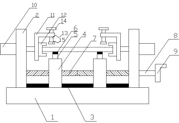
[0014] Such as figure 1 As shown, the present invention discloses a tooling fixture, including: a base 1, a side support plate 2, a guide rail 3, a slide seat 4, a support column 5, a rubber pad 6, a two-way screw rod 7, a connecting rod 8, a handle 9, Cylinder 10, L-shaped plate 11, U-shaped block 12, screw rod 13, handle 2 14, briquetting block 15, described side support plate 2 is two symmetrical vertical fixed on the left and right sides of base 1 upper end surface, and two A guide rail 3 is fixed horizontally between the two side support plates 2, the lower end surface of the guide rail 3 is fixedly connected with the upper end surface of the base 1, a sliding seat 4 is respectively arranged on the left and right sides of the guide rail 3, and two sliding seats 4 The lower end surface is provided with a groove matching the guide rail 3, and the sliding seat 4 is slidably connected with the guide rail 3 through the groove. The upper end surface of the sliding seat 4 is eve...


PUM


Abstract

The invention discloses a tool clamp. A guide rail is horizontally and fixedly connected between two side supporting plates, the left side and the right side of the guide rail are each provided with asliding base in a sliding manner, supporting columns are evenly arranged on the upper end faces of the sliding bases, the top end of each supporting column is bonded with a rubber pad, the two ends of a dual-way screw are rotatably connected with the side supporting plates on the left side and the right side through bearings, the dual-way screw horizontally penetrates the two sliding bases, the sliding bases are in threaded connection with the dual-way screw through thread holes, the left end of a connecting rod is fixedly connected with the right end of the dual-way screw, the right end of the connecting rod is fixedly connected with a first handle, upper portions of end faces, away from one side of the center of a base, of the two side supporting plates are each provided with an air cylinder, tail ends of piston rods of the air cylinders are fixedly connected with an L-shaped plate, a U-shaped clamping block is fixedly connected to the end face, facing one side of the center of thebase, of the vertical part of the L-shaped plate, a screw rod is in threaded connection to the horizontal part of the L-shaped plate, a second handle is fixedly connected to the upper end of the screwrod, and a pressing block is fixedly connected to the lower end of the screw rod. The tool clamp has the beneficial effects of being convenient to use and high in clamping stability.

Description

technical field [0001] The invention relates to a tool fixture, which is applied in the technical field of mechanical processing. Background technique [0002] Fixture refers to the device used to fix the processing object in the process of mechanical manufacturing so that it can occupy the correct position to accept construction or inspection, also known as fixture. In a broad sense, any process in the process, the device used to install the workpiece quickly, conveniently and safely, can be called a fixture. At present, some fixture structures on the market are too simple, consisting of a base and clamping devices arranged on both sides of the base. The bottom surface of the workpiece in this structure is in contact with the base, which is inconvenient for construction or inspection of the bottom surface of the workpiece, and it is not very convenient to use. , and its clamping stability is not high. Contents of the invention [0003] In order to solve the defects of t...

Claims


Application Information

Patent Timeline
Patent Type & Authority Applications(China)
IPC IPC(8): B25B11/00B23Q3/08
CPCB25B11/00B23Q3/08
Inventor 张多梅
Owner 张多梅
Why Eureka
Try Eureka