Horizontal well completion pipe string for middle-shallow oil reservoir

A technology for well completion strings and horizontal wells, which is applied in wellbore/well components, wellbore/well valve devices, earthwork drilling and production, etc., and can solve delays in construction progress, stuck in wellbore, large casing strings, etc. problem, to achieve the effect of reducing wear

Inactive Publication Date: 2018-03-09
邹跃明
View PDF0 Cites 0 Cited by
  • Summary
  • Abstract
  • Description
  • Claims
  • Application Information

AI Technical Summary

Problems solved by technology

[0002] The completion of extended-reach horizontal wells is characterized by high inclination, long open hole, and long section of stabilizing well. In the case of high inclination angle, the casing string is close to the lower well wall. After entering the horizontal section, the casing string will be completely attached On the lower well wall, the contact section between the casing string and the formation is very long at this time, and the casing string is loaded on the horizontal section of the well wall. The friction resistance of the formation to the casing string is quite large, and it cannot even go down to the bottom of the well by its own weight. , it needs to be pressurized to slide down, and it is easy to cause the casing string to buckle, and it may even cause the casing string to be stuck in the curved section of the wellbore due to the high rigidity of the casing and cannot be run in
Due to the high frictional resistance of the casing string, the casing string often cannot go down to the predetermined position smoothly, delaying the construction progress, affecting the subsequent oil recovery effect, and even causing serious consequences of wellbore scrapping

Method used


Image

  • Horizontal well completion pipe string for middle-shallow oil reservoir
  • Horizontal well completion pipe string for middle-shallow oil reservoir

Examples


Embodiment 1

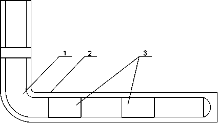
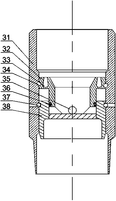
[0022] like figure 1 and figure 2 As shown, this embodiment includes a casing 1 placed in the wellbore 2, and two floating collars 3 are arranged on the horizontal section of the casing 1, and the floating collars 3 include a casing 31, an upper sliding Sleeve 32 and sliding sleeve 38, the upper sliding sleeve 32 is composed of interconnecting parts and a shearing part with the same outer diameter as the inner diameter of the housing 31, the shearing part is supported on the upper section of the inner wall of the housing 31 by the upper shear nail 34, and slides down The sleeve 38 is supported on the lower section of the inner wall of the housing 31 by the lower shear nail 37. The communication part is placed in the lower sleeve 38, and a discharge hole 35 is opened on the communication part. When the upper shear nail 34 is not cut off, The lower sleeve 38 seals the discharge hole 35, and when the upper shear nail 34 is cut off, the upper sliding sleeve 32 moves along the ax...


PUM


Abstract

The invention discloses a horizontal well completion pipe string for medium and shallow oil reservoirs, including a casing, and two floating couplings are arranged on the horizontal section of the casing, and the floating couplings include a shell, an upper sliding sleeve and a lower sliding sleeve. The upper sliding sleeve is composed of a connecting part and a shearing part. The shearing part is supported on the upper part of the inner wall of the shell by the upper shearing nail. The lowering sleeve is supported on the lower part of the inner wall of the shell by the lower shearing nail. The connecting part is placed in the lowering sleeve. , and a discharge hole is opened on the connecting part; an annular stabilizing groove is opened on the upper end surface of the shearing part, and the groove width of the stabilizing groove decreases gradually along the axial direction of the shearing part. By adding multiple floating collars on the casing, the casing is kept full of air. Since the casing below the floating collar is filled with air, after this section of casing enters the horizontal well section, the gravity acting on the horizontal well wall is reduced. , the friction between the casing and the well wall decreases accordingly, and the thrust to push the casing forward also decreases, which helps to improve the cementing quality of the horizontal section and facilitates running the casing to the designed position.

Description

technical field [0001] The invention relates to the field of petroleum exploitation, in particular to a horizontal well completion pipe string used for medium and shallow oil reservoirs. Background technique [0002] The completion of extended-reach horizontal wells is characterized by high inclination, long open hole, and long section of stabilizing well. In the case of high inclination angle, the casing string is close to the lower well wall. After entering the horizontal section, the casing string will be completely attached On the lower well wall, the contact section between the casing string and the formation is very long at this time, and the casing string is loaded on the horizontal section of the well wall. The friction resistance of the formation to the casing string is quite large, and it cannot even go down to the bottom of the well by its own weight. , It needs to be pressurized to slide down, and it is easy to cause the casing string to buckle, and it may even c...

Claims


Application Information

Patent Timeline
Patent Type & Authority Applications(China)
IPC IPC(8): E21B33/13E21B34/08
CPCE21B33/13E21B34/08
Inventor 邹跃明
Owner 邹跃明
Why Eureka
Try Eureka