Mixed compensating type subaperture spliced surface shape detection method

A technology of surface shape detection and aperture splicing, which is applied to measuring devices, instruments, and optical devices, etc., can solve the problems of increased operation time cost of detection operation data, high manufacturing cost of lens compensator, and rising economic cost, so as to reduce splicing. The effect of error transmission and accumulation, time cost reduction, and economic cost reduction

Active Publication Date: 2018-03-09
CHANGCHUN INST OF OPTICS FINE MECHANICS & PHYSICS CHINESE ACAD OF SCI
View PDF6 Cites 16 Cited by
  • Summary
  • Abstract
  • Description
  • Claims
  • Application Information

AI Technical Summary

Problems solved by technology

For lens-compensated sub-aperture splicing detection, since the lens compensator is composed of at least two lenses, it is inevitable to introduce adjustment errors, and the reference surface of the compensator is generally an aspheric surface, which is not only difficult to process, but also requires additional Therefore, the manufacturing cost of large-diameter lens compensators is high. When inspecting super-large-diameter convex aspheric surfaces, different compensators need to be manufactured for different annular zones, which greatly increases the inspection cost; and for CGH compensators 3 For example, limited by the existing manufacturing process of CGH, its manufacturing diameter generally does not exceed 200mm under the condition of ensuring accuracy. With the increase of the diameter of the convex aspheric surface, when the diameter is larger than 1m, more rings are required. The sub-aperture covers it with full aperture, which not only brings about the increase of time cost in detection operation and data calculation, but more importantly, the increase in economic cost caused by the need to manufacture corresponding compensation devices for different sub-apertures

Method used


Image

  • Mixed compensating type subaperture spliced surface shape detection method
  • Mixed compensating type subaperture spliced surface shape detection method
  • Mixed compensating type subaperture spliced surface shape detection method

Examples


Embodiment Construction

[0029] The present invention will be described in detail below with reference to the accompanying drawings and examples.

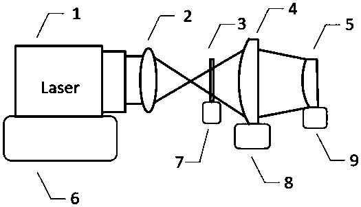
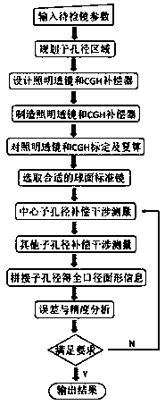
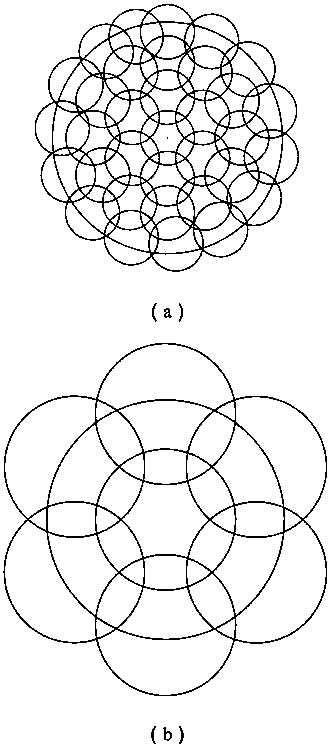
[0030] The present invention proposes a method for detecting the surface shape of a super-large-diameter convex aspheric surface (above 500 mm in diameter) mirror, and realizes surface shape detection based on sub-aperture splicing and compensation detection, and the compensation detection method of the present invention combines CGH compensation and lens compensation A hybrid compensation method formed in combination can expand the area of ​​a single sub-aperture measurement under the condition of using a smaller CGH compensator 3, thereby effectively reducing the number of required sub-apertures, reducing the transmission of errors and reducing all The number of compensators required. The benefits brought by the reduction in the number of sub-apertures are: a. reducing the time cost required for optical element adjustment and subsequent splicing calculat...


PUM


Abstract

The invention discloses a mixed compensating type sub-aperture spliced surface shape detection method. During the sub-aperture spliced surface shape detection process, the area of the single sub-aperture measurement is enlarged on the premise that a small CGH compensator is adopted. Therefore, the number of required sub-apertures is effectively reduced. The error transmission is reduced, and the number of the required compensators is reduced at the same time. The sub-aperture splicing detection means is combined with the mixed compensation means of a lens and a CGH compensator, so that the usage constraint of the adopted CGH compensator within a single compensation detection region, namely a sub-aperture range, can be avoided. The number of sub-apertures required by the convex aspheric surface of the same specification is reduced. As a result, the time cost needed by optical element adjustment and subsequent splicing calculation is reduced. Meanwhile, the number of required CGH compensators is reduced. The detection economic cost is reduced. The transmission and the accumulation of splicing errors are reduced, and the detection precision is improved.

Description

technical field [0001] The invention relates to the technical field of mirror surface detection, in particular to a hybrid compensation type sub-aperture splicing surface shape detection method. Background technique [0002] Due to the increase in the degree of freedom, aspheric optical elements have significant advantages in correcting aberrations, improving image quality, and reducing the size and quality of imaging systems. Therefore, aspheric optical elements are becoming more and more popular. It is used in space optics, military defense, high-tech civilian and other fields. Especially in the field of space optics, the secondary mirrors of astronomical telescopes are usually super-large-diameter convex aspheric mirrors. For example, the secondary mirror of the JWST Space Telescope, which is about to replace the Hubble Telescope, has reached 738mm, and the secondary mirrors of some ground-based astronomical telescopes are even larger. As high as several meters, for exam...

Claims


Application Information

Patent Timeline
Patent Type & Authority Applications(China)
IPC IPC(8): G01B11/24
CPCG01B11/2441
Inventor 王孝坤张海东薛栋林张学军
Owner CHANGCHUN INST OF OPTICS FINE MECHANICS & PHYSICS CHINESE ACAD OF SCI
Why Eureka
Try Eureka