Vacuum cleaner system

A technology for vacuum cleaners and chargers, which is applied in the field of vacuum cleaner systems and two-in-one vacuum cleaners. It can solve the problems of reducing the power transmission between vacuum cleaners and chargers, and achieve the effect of shortening the manufacturing time.

Active Publication Date: 2018-03-09
AB ELECTROLUX
View PDF10 Cites 0 Cited by
  • Summary
  • Abstract
  • Description
  • Claims
  • Application Information

AI Technical Summary

Problems solved by technology

The problem with contacting elements may be that elements on the charger and / or vacuum may be affected by dirt, which would reduce contact and thereby reduce power transfer between the vacuum and charger
Another issue may be the need for additional holes and / or fastenings in / on the housing of the vacuum cleaner and / or charger

Method used


Image

  • Vacuum cleaner system
  • Vacuum cleaner system
  • Vacuum cleaner system

Examples


Embodiment Construction

[0043] The present invention will now be described more fully with reference to these drawings, in which a number of exemplary embodiments are shown. However, the present invention should not be construed as being limited to the embodiments set forth herein. Throughout the following description, when applicable, similar reference numbers are used to denote similar elements, components, items, or features.

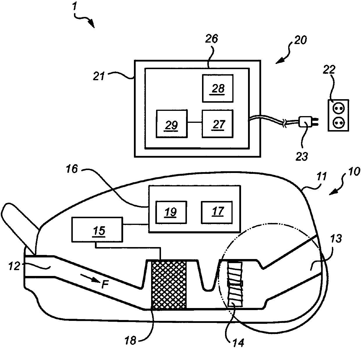
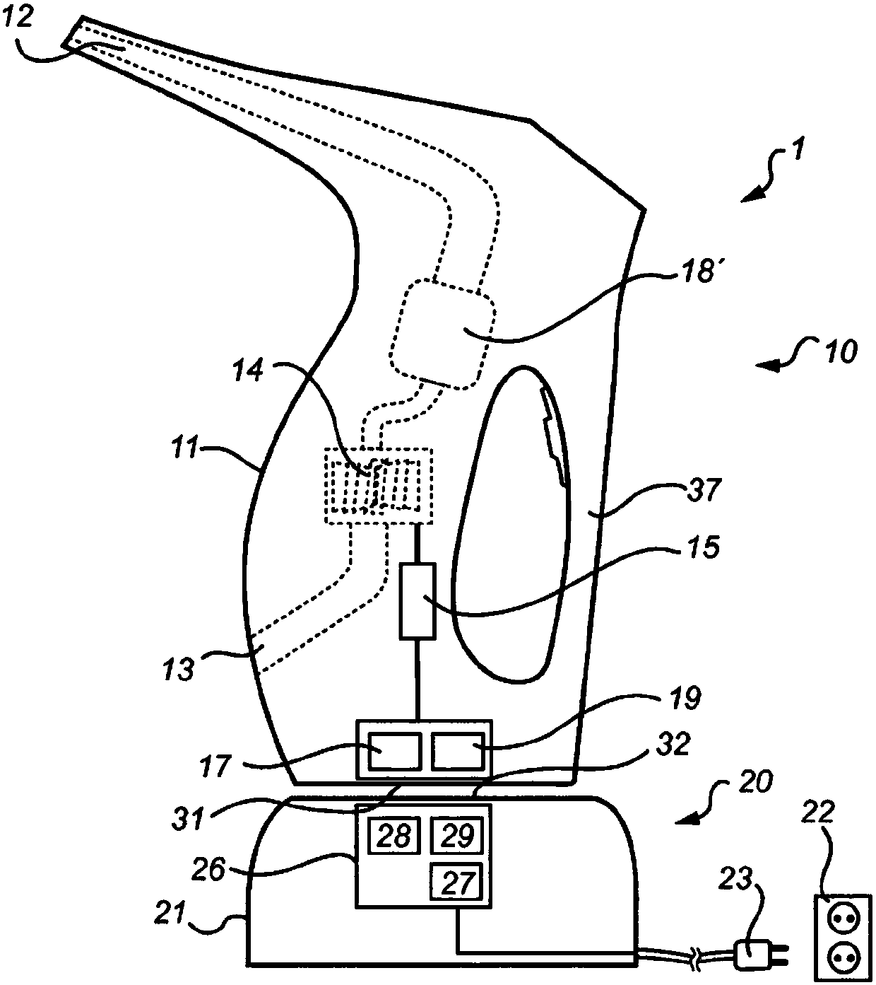
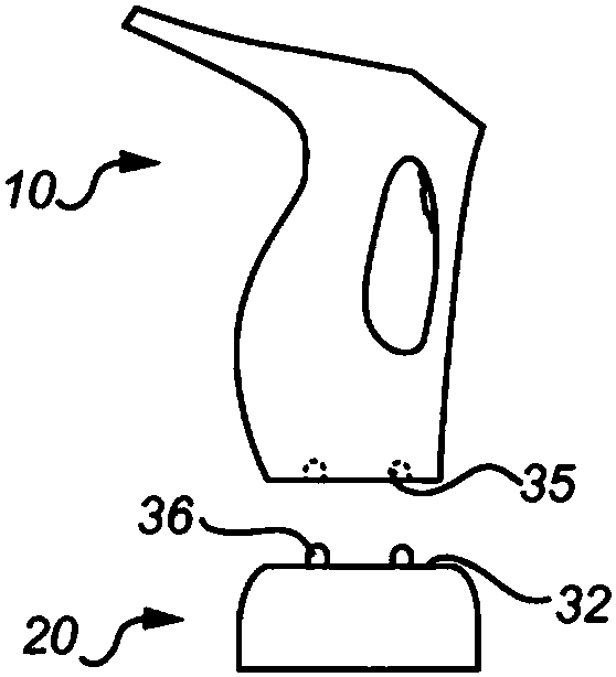
[0044] figure 1 A vacuum cleaner system (1) is shown. The vacuum cleaner system (1) includes: a vacuum cleaner (10), such as a robot vacuum cleaner, a handheld vacuum cleaner, a stick vacuum cleaner, a vertical vacuum cleaner, or a horizontal vacuum cleaner; and a charger (20). The vacuum cleaner (10) includes a first housing (11). The first housing (11) includes an air inlet (12), an air outlet (13), and a motor fan unit (14) for generating air flow (F) from the air inlet (11) to the air outlet (12) . The air flow (F) generated by the motor fan unit (14) transports dust a...


PUM


Abstract

The invention relates to vacuum system (1) comprising a vacuum cleaner (10) comprising a first housing (11) comprising an air inlet (12), an air outlet (13), a motor fan unit (14) for creating an airflow (F) from the air inlet (12) to the air outlet (13), a battery (15) for powering the motor fan unit (14), and a first unit (16) for charging the battery (15), and a charger (20) comprising a secondhousing (21) comprising a second unit (26) for changing the battery (15), wherein the first unit (16) is connected to the battery (15) and the second unit (26) is adapted to be connected to an external power source (22), and the first unit (16) and the second unit (26) are adapted for wireless power transfer from the second unit (26) to the first unit (16).

Description

[0001] The present invention relates generally to the field of vacuum cleaners. More specifically, the present invention relates to a vacuum cleaner system including a vacuum cleaner and a charger. The vacuum cleaner includes a first housing that includes an air inlet, an air outlet, a motor fan unit for generating air flow from the air inlet to the air outlet, and power for the motor fan unit The battery and the first unit for charging the battery. The charger includes a second housing that includes a second unit for charging the battery. The first unit and the second unit are adapted to wirelessly transmit power from the second unit to the first unit. Preferably, the first unit includes a first coil connected to the battery, and the second unit includes a second coil adapted for connection to an external power source. Background technique [0002] Vacuum cleaner systems are well known in the prior art. The vacuum cleaner system generally includes a vacuum cleaner (typically...

Claims


Application Information

Patent Timeline
Patent Type & Authority Applications(China)
IPC IPC(8): A47L5/22A47L5/24A47L5/28A47L5/36A47L9/28H02J7/00H02J7/02H02J50/10H02J50/90
CPCH02J7/025H02J50/90H02J50/10A47L5/225A47L5/24A47L5/28A47L5/362A47L9/2873A47L9/2884H02J7/0042A47L2201/022A47L9/2894H02J7/0044
Inventor C·尼贝里米凯尔·佩尔松P·亚尔马松J·齐塔H·特罗贝里
Owner AB ELECTROLUX
Why Eureka
Try Eureka