Dust collector

A vacuum cleaner and dust collection technology, applied in the direction of vacuum cleaners, suction filters, suction nozzles, etc., can solve the problems of insufficient lightness of operation, operation fatigue, inconvenient movement, etc., achieve flexible and light operation, reduce grip force, and facilitate heat dissipation.

Active Publication Date: 2018-03-13
PANASONIC APPLIANCES CHINA CO LTD
View PDF6 Cites 3 Cited by
  • Summary
  • Abstract
  • Description
  • Claims
  • Application Information

AI Technical Summary

Problems solved by technology

[0002] With the diversification of family life needs, different families have different needs for home decoration, and the difficulty of cleaning complex decorations increases. Generally, vacuum cleaners are used to clean them to avoid the impact of washing or wiping on home decoration. Traditional vacuum cleaners are heavy and mobile. The problem of inconvenience, the existing technology provides various types of portable vacuum cleaners, which reduce the volume and weight of the vacuum cleaners, which is convenient for users to operate to a certain extent, but the dustbin of such portable vacuum cleaners is located at the front of the housing, and the motor and battery are located in the housing The center of gravity of the entire vacuum cleaner is towards the rear end. During use, the user must hold up the rear part to control the air inlet to move accurately to the area to be cleaned, so it is easy to cause user fatigue, and the operation is still not light enough.

Method used


Image

  • Dust collector
  • Dust collector
  • Dust collector

Examples


Embodiment Construction

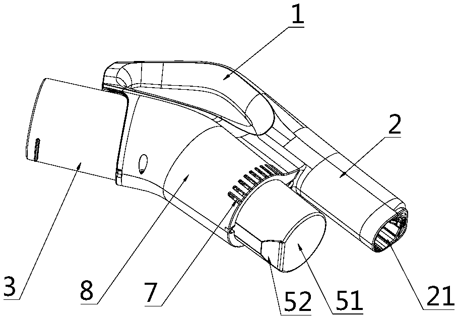
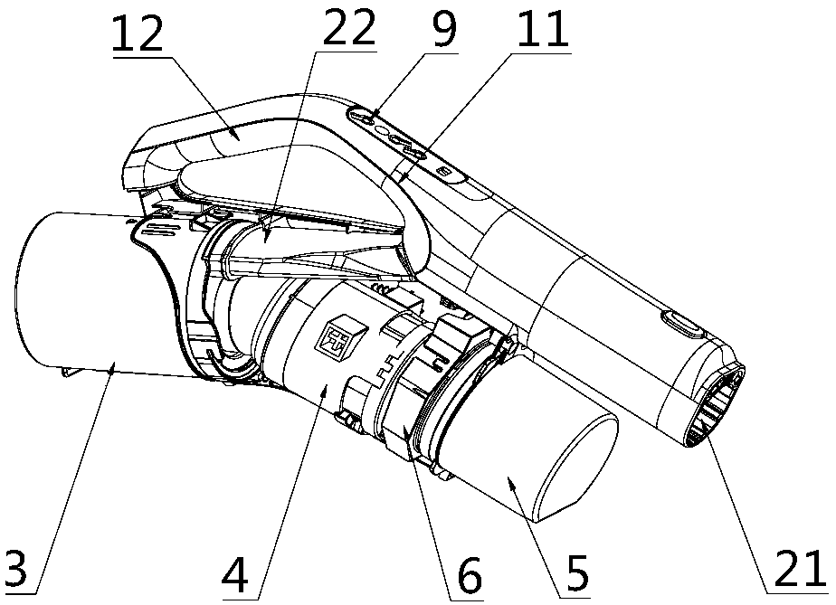
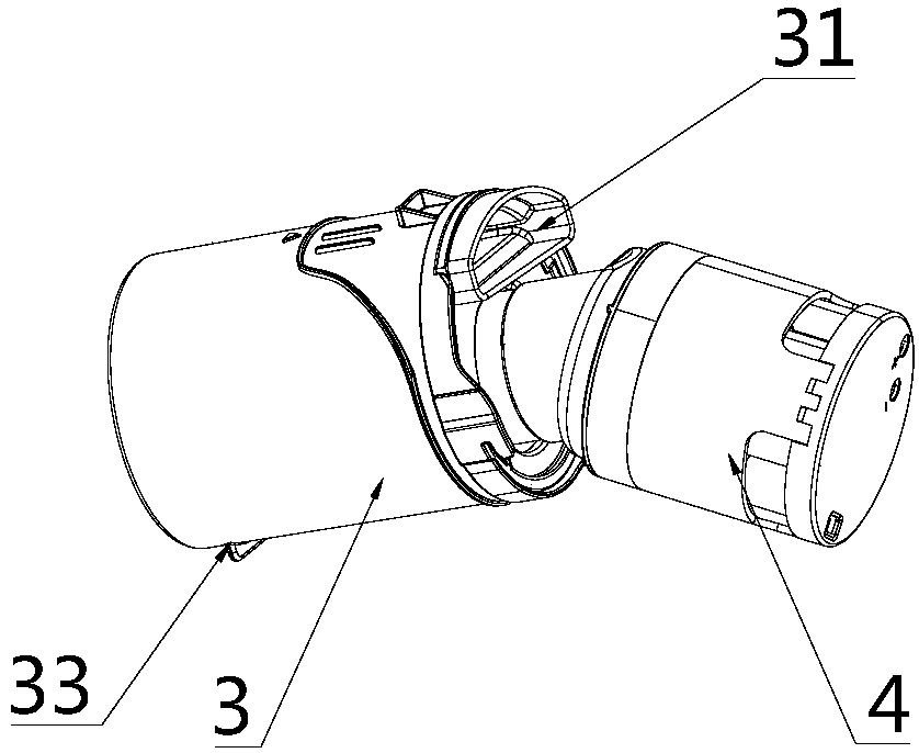
[0027] The invention provides a vacuum cleaner, such as Figure 1 to Figure 4 As mentioned above, it includes a handle assembly and a dust collection assembly. The handle assembly includes a handle 1 and a connecting pipe 2 connected to the front end of the handle 1. The front end of the connecting pipe 2 is provided with an air inlet 21, and the dust collection assembly is connected to the handle assembly. , the dust collection assembly includes a dustbin 3, a motor 4 and a battery 5, a control circuit board 6 is arranged between the motor 4 and the battery 5, the battery 5 is electrically connected to the motor 4 through the control circuit board 6, and the dustbin 3 has an air inlet 31 and the air outlet 32, the dustbin 3, the motor 4 and the battery 5 are arranged sequentially from the back to the front, the air inlet 31 of the dustbin 3 communicates with the rear end of the connecting pipe 2, and the dustbin 3 is positioned at the rear of the connecting pipe 2, The front ...


PUM


Abstract

The invention discloses a dust collector, belongs to the technical field of household appliances and solves the problem of inconvenience in operation of a dust collector in the prior art. The technical scheme for solving the problem mainly comprises a handle assembly and a dust collecting assembly. The handle assembly includes a handle and a connecting pipe connected at the front end of the handle. A wind inlet is arranged at the front end of the connecting pipe. The dust collecting assembly is connected onto the handle assembly. The dust collecting assembly includes a dustbin, a motor and a battery. The dustbin has an air inlet and an air outlet. The motor and the battery are electrically connected. The dustbin, the motor and the battery are arranged in sequence from the back to the front. The air inlet of the dustbin communicates with the rear end of the connecting pipe. The dustbin is located behind the connecting pipe. A wind outlet communicating with the air outlet is arranged inthe front end of the dust collecting assembly. The wind outlet is located in front of the motor. The dust collector in the invention not only reduces the holding force of an arm holding the handle tomake the user's operation more flexible and effortless, but also facilitates the heat dissipation of the motor.

Description

technical field [0001] The invention relates to the technical field of household appliances, in particular to a vacuum cleaner. Background technique [0002] With the diversification of family life needs, different families have different needs for home decoration, and the difficulty of cleaning complex decorations increases. Generally, vacuum cleaners are used to clean them to avoid the impact of washing or wiping on home decoration. Traditional vacuum cleaners are heavy and mobile. The problem of inconvenience, the existing technology provides various types of portable vacuum cleaners, which reduce the volume and weight of the vacuum cleaners, which is convenient for users to operate to a certain extent, but the dustbin of such portable vacuum cleaners is located at the front of the housing, and the motor and battery are located in the housing The center of gravity of the entire vacuum cleaner leans toward the rear end. During use, the user must hold up the rear part to co...

Claims


Application Information

Patent Timeline
Patent Type & Authority Applications(China)
IPC IPC(8): A47L9/00A47L9/10A47L9/32A47L9/02
CPCA47L9/00A47L9/02A47L9/10A47L9/32
Inventor 陈娴邵晓磊叶丰荣
Owner PANASONIC APPLIANCES CHINA CO LTD
Why Eureka
Try Eureka