Self-adaption ultrasonic beamforming method and system based on channel data

A channel data, ultrasonic technology, applied in the direction of ultrasonic/sonic/infrasonic wave diagnosis, acoustic wave diagnosis, infrasonic wave diagnosis, etc., can solve the problem that signal sidelobe, noise and strong reflection signal cannot be completely eliminated, signal sidelobe and electronic noise cannot be completely eliminated , It is impossible to remove noise and unwanted signals, etc., to achieve good signal detection effect, improve noise removal efficiency, and suppress signal effects

Active Publication Date: 2018-03-13
SASET CHENGDU TECH LTD
View PDF7 Cites 13 Cited by
  • Summary
  • Abstract
  • Description
  • Claims
  • Application Information

AI Technical Summary

Problems solved by technology

[0006] 1. The traditional hardware beamforming method needs to pre-define the transmission and reception delay curves. The signals after beamforming are stored in the form of connecting beams one by one, which cannot achieve point-by-point focusing of transmission.
To remove sidelobes, unwanted signal reflections, and electronic noise, traditional beamforming relies on summing all channel data after applying a time delay, which cannot achieve the purpose of removing noise and unwanted signals due to directivity issues
[0007] 2. The existing related software beamforming technology mainly uses the retrospective method of multiple transmissions. By saving the channel data obtained from multiple transmissions, and then using software to synthesize (using a certain weighting), it is difficult to remove noise in the time domain. At the same time, useful signals are reserved for signal sidelobe and electronic noise suppression, but signal sidelobe, noise and strong reflection signals cannot be completely eliminated

Method used


Image

  • Self-adaption ultrasonic beamforming method and system based on channel data
  • Self-adaption ultrasonic beamforming method and system based on channel data
  • Self-adaption ultrasonic beamforming method and system based on channel data

Examples


Embodiment Construction

[0027] In the following, the present invention will be further described in detail in conjunction with the accompanying drawings and embodiments, so as to make the purpose, technical solutions and advantages of the present invention more clear. It should be understood that the specific embodiments described here are only used to explain the present invention, not to limit the present invention.

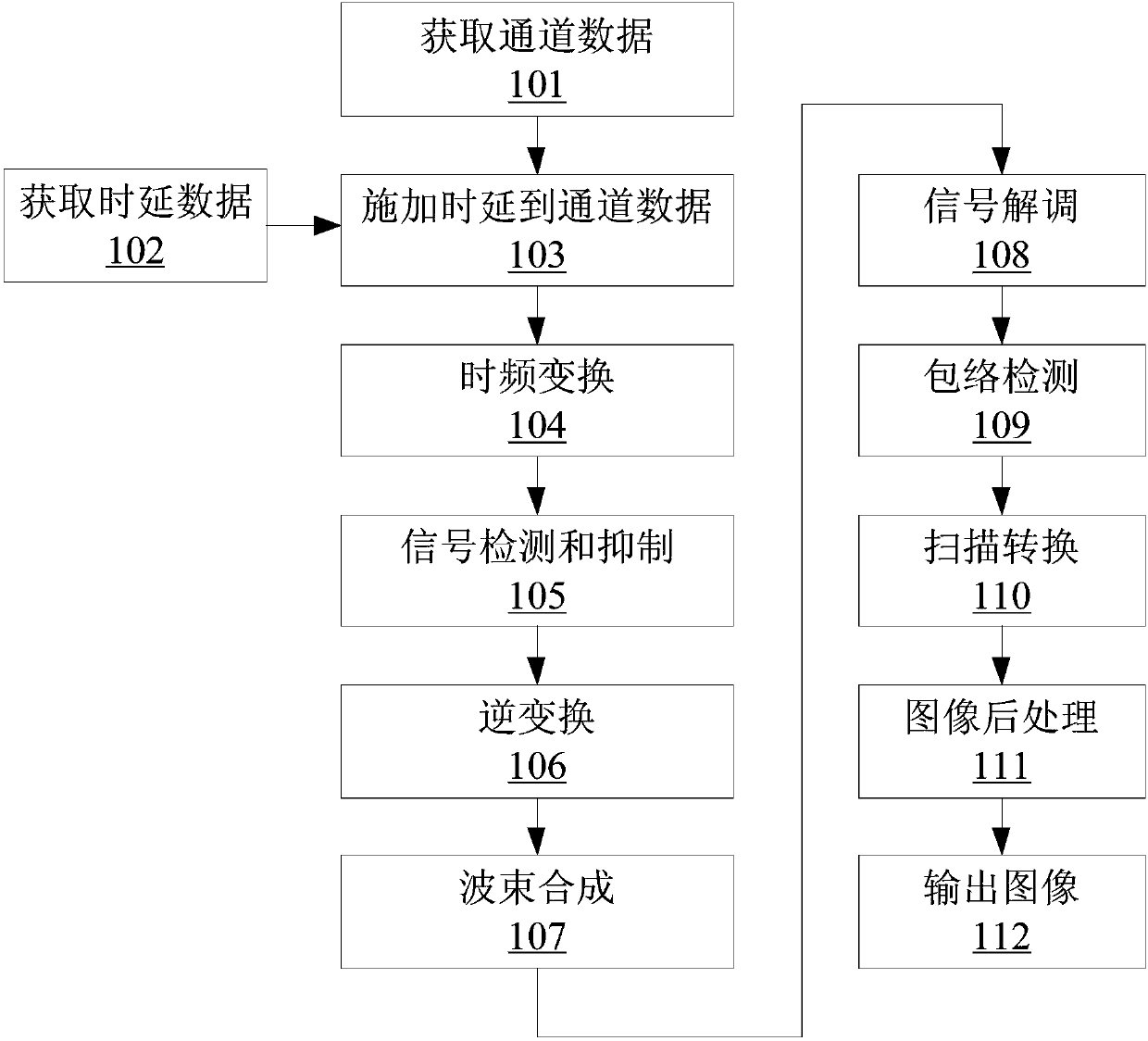
[0028] figure 1 A flow chart of an adaptive ultrasonic beam forming method based on channel data according to an embodiment of the present invention is shown. Part or all of the following steps included in it can be executed independently or in parallel, and the step numbers are only used to identify each step, and are not used to limit the execution order and / or times of each step.

[0029] Step 101: Perform multiple ultrasonic transmissions, and obtain first channel data according to the corresponding multiple echo signals

[0030] For example, according to different application c...


PUM


Abstract

The invention discloses a self-adaption ultrasonic beamforming method and system based on channel data. Unwished sidelobes can be removed, noise generated by the channel data can be stored, and the removing efficiency is high. The method comprises the steps of conducting multiple times of ultrasonic emission, and obtaining first channel data according to corresponding multiple echo signals; obtaining time delay data corresponding to each focus point; regarding each focus point, applying the corresponding time delay to the first channel data to obtain vector data; conducting discrete time-frequency transformation on one or multiple vectors in the vector data to generate frequency domain signals; conducting inverse transformation on each vector in the frequency domain signals which are subjected to noise suppression to obtain second channel data; conducting beamforming on the obtained second channel data; conducting signal demodulation, envelope detection, scanning conversion and image postprocessing on signals which are subjected to beamforming in sequence to generate a frame of image.

Description

technical field [0001] The invention relates to the technical field of ultrasonic imaging, in particular to an adaptive ultrasonic beam synthesis method and system based on channel data. Background technique [0002] In the medical ultrasound imaging system, from the ultrasound probe to the final display of the image, it must go through the transmission and reception circuit, analog signal to digital signal conversion, beam synthesis, signal baseband processing, digital scan converter and image post-processing and other links. Among them, the beamforming quality of the ultrasound imaging system has a crucial impact on the final imaging effect. The main processing methods of beamforming channel data include traditional hardware beamforming and software beamforming emerging with the development of general-purpose processor capabilities. The related technologies involved include electronic focusing and scan line control, apodization, variable aperture, etc. Whether it is hardw...

Claims


Application Information

Patent Timeline
Patent Type & Authority Applications(China)
IPC IPC(8): A61B8/00
CPCA61B8/52A61B8/5207A61B8/5269
Inventor 刘西耀石丹刘东权
Owner SASET CHENGDU TECH LTD
Why Eureka
Try Eureka