
Manual-pneumatic control system for packaging machinery

A technology of pneumatic control system and packaging manipulator, applied in the field of machinery

Inactive Publication Date: 2018-03-13
赵俭
View PDF0 Cites 0 Cited by
  • Summary
  • Abstract
  • Description
  • Claims
  • Application Information

AI Technical Summary

Problems solved by technology

3) In the packaging process, multiple actions are often coordinated, and the pneumatic components are easy to adjust

Method used


Image

  • Manual-pneumatic control system for packaging machinery
  • Manual-pneumatic control system for packaging machinery
  • Manual-pneumatic control system for packaging machinery

Examples


Embodiment Construction

[0014] The present invention will be further described below in conjunction with drawings and embodiments.

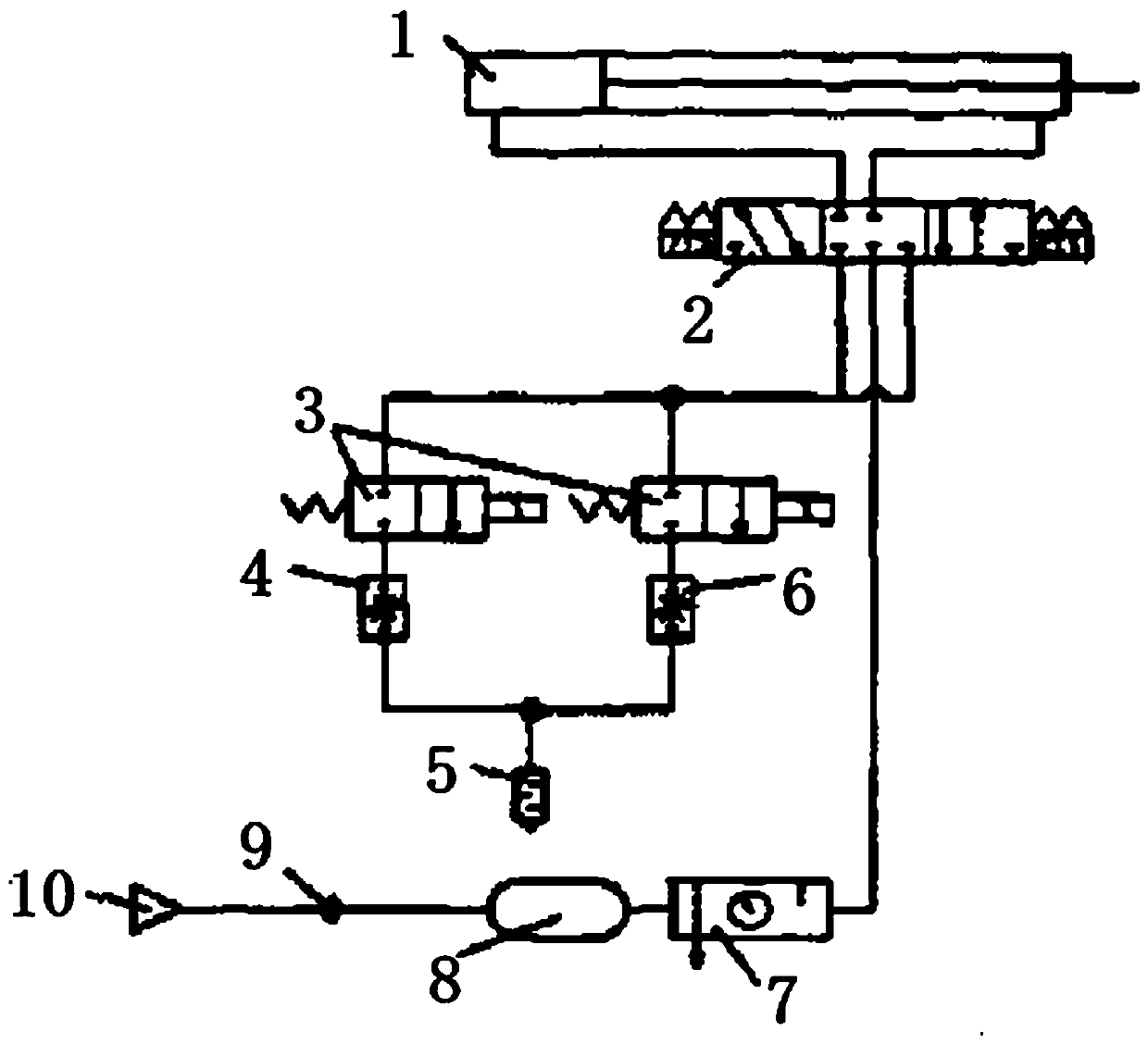
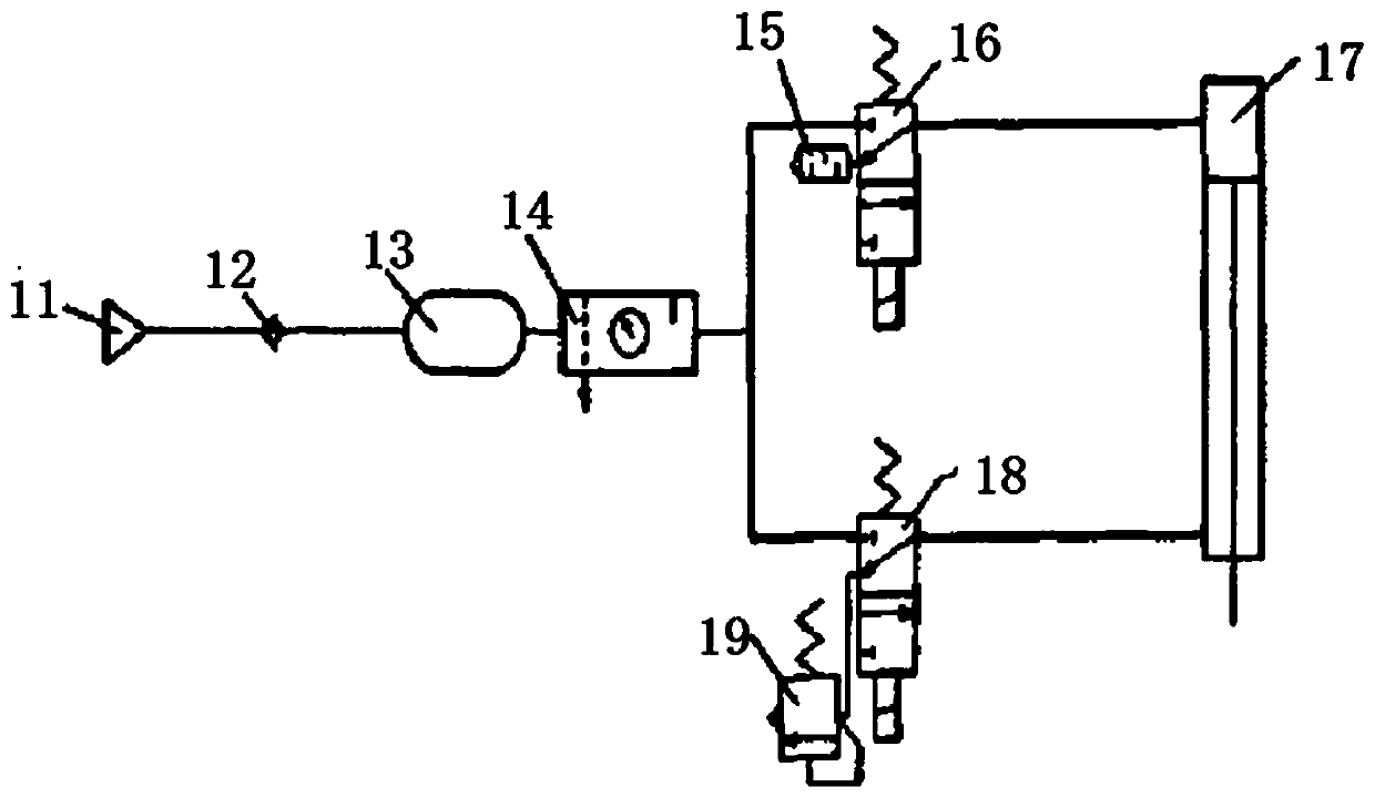
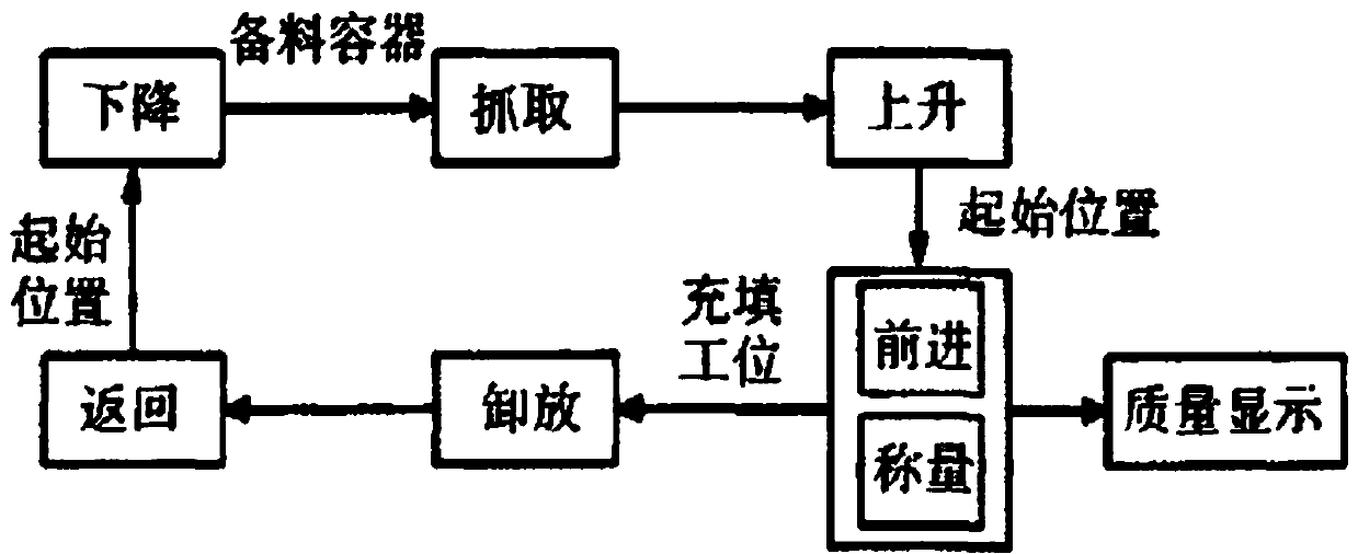
[0015] Such as figure 1 , the design goal is to realize continuous automatic packaging filling and metering of short and small filamentary materials, and the executive parts make cyclical linear horizontal and vertical movements, and the speed must be adjusted during the movement.

[0016] Such as figure 2 , The pneumatic control system includes the horizontal motion drive system of the packaging filling manipulator, the vertical motion drive system and the extension and contraction drive system of the material hand. The packaging and filling manipulator needs to make fixed-distance circular reciprocating motion between two fixed points in the horizontal direction, and the speed should be fast under the acceptable impact. Therefore, a double-acting cylinder with a buffer and an inductive switch is used as the actuator. The pilot-operated 3-position 5-way double sole...


PUM


Abstract

A packaging manipulator pneumatic control system includes a packaging filling manipulator device horizontal movement drive system, a vertical movement drive system and a material hand extension and contraction drive system. The pneumatic control manipulator device can be used to realize automatic filling, and an automatic weighing system can be configured in the device to complete automatic measurement, so that the whole packaging process can run automatically and continuously.

Description

Technical field [0001] The invention relates to a pneumatic control system for a packaging manipulator, which is suitable for the mechanical field. Background technique [0002] Survey data statistics show that 90% of packaging machinery uses pneumatic components and pneumatic systems. Pneumatic technology has incomparable advantages in packaging machine technology compared with other power drive technologies: 1) Pneumatic actuators are mainly used to complete actions such as selection, collection, loading, clamping and unloading, and the design and manufacture of complex packaging systems, using pneumatic technology , can greatly simplify the whole mechanism. 2) The working medium is air, and the pneumatic device is a clean power source. In places with strict restrictions on pollution, the pneumatic system is preferred. 3) In the packaging process, coordination of multiple actions is often required, and the pneumatic components are easy to adjust. 4) Since the pneumatic ...

Claims


Application Information

Patent Timeline
IPC IPC(8): B25J9/20
CPCB25J9/20
Inventor 赵俭
Owner 赵俭
Learn More