Vane wheel lifting appliance for wind generating set and vane wheel lifting method

A technology for a wind turbine generator set and a hoisting method, which is applied to wind turbines, wind energy power generation, and wind turbines that are consistent with the wind direction, etc., can solve problems such as difficulty in dismantling and loosening 501 of the sling knot, the large trailing edge 201, and affecting the hoisting of the impeller. , to achieve the effect of improving safety, stability and reliability, improving stability and reliability, and convenient installation and disassembly

Active Publication Date: 2018-03-13
URUMQI GOLDWIND TIANYI WIND POWER CO LTD
View PDF4 Cites 7 Cited by
  • Summary
  • Abstract
  • Description
  • Claims
  • Application Information

AI Technical Summary

Problems solved by technology

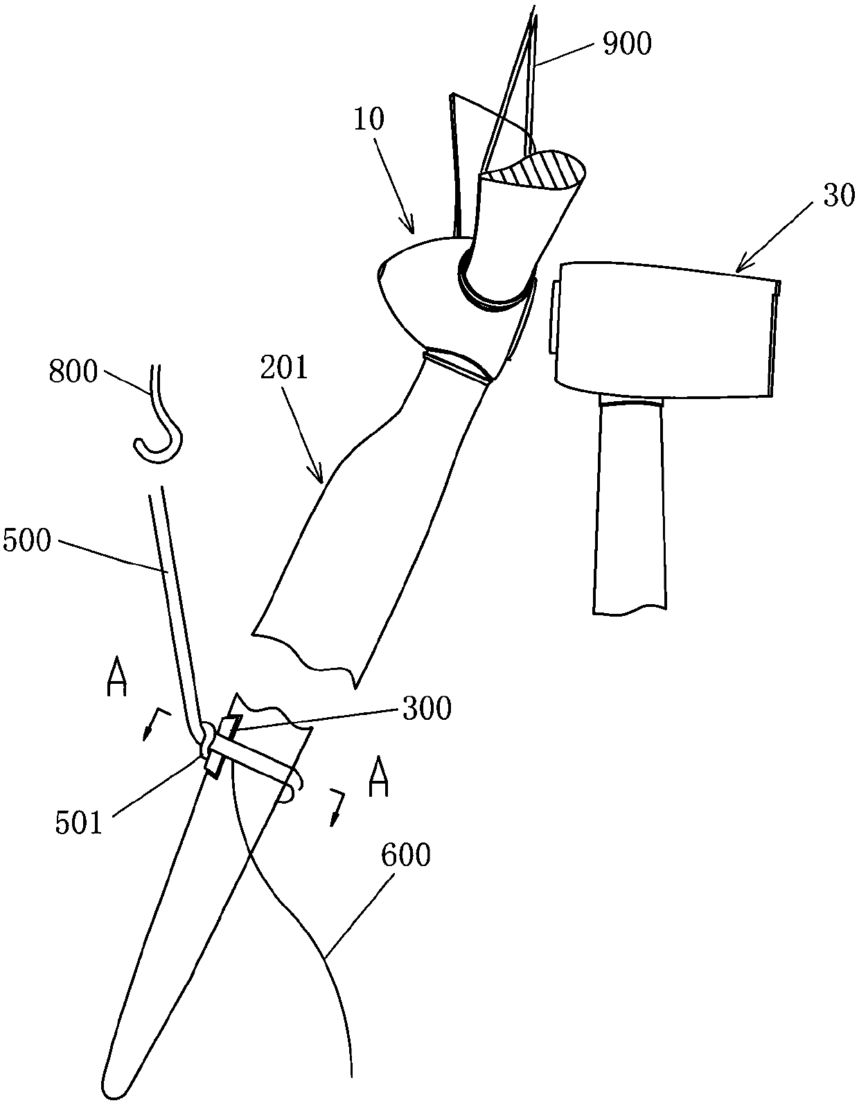
[0004] ⑴Difficulty in disassembling the auxiliary sling 500 and its consequences
[0005] At present, wind power generators are constantly being developed and manufactured in the direction of large-scale units. As the weight and shape of the impeller 10 of the wind power generator continue to increase, the pulling force on the auxiliary sling 500 also increases during the turning process of the impeller. Therefore, the auxiliary sling 500 The width of the sling is also increased, which makes the sling buckle 501 of the auxiliary sling 500 pulled tighter. The wider the auxiliary sling 500 and the greater the pulling force, the more difficult it is for the sling sling 501 to be loosened. Sometimes several people pull hard at the same time. The rope 600 is difficult to loosen the sling knot buckle 501, which takes time and wastes manpower in the impeller hoisting
The impeller hoisting is carried out in light windy weather. If there is a problem in a certain link during the impeller hoisting process and time is wasted, then it is likely to encounter strong winds in the subsequent installation stage, which will seriously affect the impeller hoisting; and the crane The fee is charged according to the time of the shift. The time-consuming disassembly of the auxiliary sling is equivalent to an increase in the cost of hoisting.
[0006] (2) The trailing edge 201 of the blade 200 at the lifting point is subjected to a large force
The protector 300 will gradually deform with the increase in the number of uses and improper use. For example, the opening angle increases, thus changing the original design surface of the protector 300 in contact with the blade 200. However, the trailing edge 201 of the blade 200 is almost a curved surface , the V-shaped armor 300 is a plane, and the two cannot be in good contact with each other to reduce or change the force-bearing surface, so the force on the trailing edge 201 will increase (especially when the trailing edge 201 of the blade 200 is downward. In the hoisting method, the force of the protective device 300 on the trailing edge 201 of the blade 200 is very large), so the existing protective device 300 cannot protect the blade 200 well, and it is likely to damage the trailing edge 201 of the blade 200
[0008] ⑶ It is difficult to support the blade 200
If the trailing edge 201 of the blade 200 is placed downward after the impeller group is completed, since the trailing edge 201 is relatively thin, the pressure of gravity on the trailing edge 201 will be very large, which will cause damage to the trailing edge 201, such as Figure 7 and Figure 8 shown
In addition, the larger the blade 200, the heavier the impeller 10 and the higher the distance from the ground. Especially in windy weather, the safety of the impeller 10 placed on the ground cannot be guaranteed.

Method used


Image

  • Vane wheel lifting appliance for wind generating set and vane wheel lifting method
  • Vane wheel lifting appliance for wind generating set and vane wheel lifting method
  • Vane wheel lifting appliance for wind generating set and vane wheel lifting method

Examples


Embodiment Construction

[0051] Embodiments of the invention will now be described more fully with reference to the accompanying drawings, in which exemplary embodiments of the invention are shown.

[0052] The following will combine Figure 9 to Figure 16 The impeller hanger 20 according to the exemplary embodiment of the present invention is described. Figure 9 is a left view of the wind turbine rotor hanger according to an exemplary embodiment of the present invention; Figure 10 is a front view of a rotor hanger for a wind power generating set according to an exemplary embodiment of the present invention; Figure 11 is a right side view of the wind turbine hanger of the wind power generating set according to the exemplary embodiment of the present invention; Figure 12 yes Figure 11 Enlarged view of part I shown in ; Figure 13 yes Figure 11 Enlarged view of Part II shown in ; Figure 14 is an exploded perspective view of a rotor hanger of a wind power generating set according to an exemp...


PUM


Abstract

The invention provides a vane wheel lifting appliance for a wind generating set and a vane wheel lifting method. The vane wheel lifting appliance comprises a fist clamp module, a second clamp module,an air cushion controller and one or more lifting lugs, wherein the fist clamp module comprises a first clamp shell and a first air cushion, and the first air cushion is arranged on the surface of theinner side of the first clamp shell. The second clamp module comprises a second clamp shell and a second air cushion, and the second air cushion is arranged on the surface of the inner side of the second clamp shell. The air cushion controller is arranged on the first clamp shell and / or the second clamp shell so that the first air cushion and the second air cushion can be controlled to be inflated or exhausted. The lifting lugs are mounted on the surface of the outer side of the first clamp shell or the second clamp shell, wherein the first clamp shell is detachably combined with the second clamp shell, and under the state that the first clamp shell is combined with the second clamp shell, the first air cushion is opposite to the second air cushion. By means of the vane wheel lifting appliance for the wind generating set and the vane wheel lifting method, the vane wheel lifting appliance is convenient to mount and dismount; and in addition, safety, stability and reliability of supporting and lifting of vane wheels can be improved.

Description

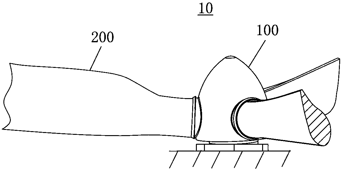
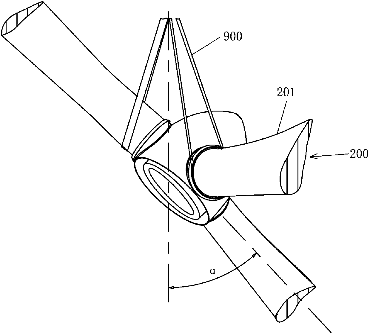
technical field [0001] The invention relates to the technical field of wind power generation, and more particularly, to an impeller hoisting tool and an impeller hoisting method for a wind power generating set. Background technique [0002] After assembling the three blades 200 on the hub 100 to form an integral impeller 10 on the ground to complete the impeller pair of the wind power generating set, the impeller 10 is placed in a horizontal state. Installing the impeller 10 placed in this way into the nacelle 30 needs to go through three steps in order to complete: turning over the impeller, hoisting in place (hanging to the height of the nacelle) and installation (flange connection). Turning over the impeller is commonly referred to as turning over the impeller: turning the impeller 10 in a horizontal state by a certain angle a, so that the impeller 10 is in a state where the first blade and the second blade are up and the third blade is down (ie, the hoisting state). Due...

Claims


Application Information

Patent Timeline
Patent Type & Authority Applications(China)
IPC IPC(8): B66C1/46F03D1/06
CPCB66C1/108B66C1/46F03D1/06Y02E10/72
Inventor 张新旺陈锋
Owner URUMQI GOLDWIND TIANYI WIND POWER CO LTD
Why Eureka
Try Eureka