
An optical cable fixing device for an optical cable fusion splice box

A technology for fixing devices and optical cables, which is applied in the coupling of optical waveguides, optics, and light guides, and can solve problems such as being easily pulled out by external forces and inconvenient operation of fixing devices

Active Publication Date: 2020-08-07
NINGBO ZHANTONG TELECOM EQUIP INDAL
View PDF7 Cites 0 Cited by
  • Summary
  • Abstract
  • Description
  • Claims
  • Application Information

AI Technical Summary

Problems solved by technology

[0004] The purpose of the present invention is to solve the problem that the fixing device of the optical cable fusion splice box in the prior art is inconvenient to operate and is easy to be pulled out by external force, and proposes a kind of optical cable fixing device for the optical cable fusion splice box

Method used


Image

  • An optical cable fixing device for an optical cable fusion splice box
  • An optical cable fixing device for an optical cable fusion splice box
  • An optical cable fixing device for an optical cable fusion splice box

Examples


Embodiment Construction

[0018] The following will clearly and completely describe the technical solutions in the embodiments of the present invention with reference to the accompanying drawings in the embodiments of the present invention. Obviously, the described embodiments are only some, not all, embodiments of the present invention.

[0019] In describing the present invention, it should be understood that the terms "upper", "lower", "front", "rear", "left", "right", "top", "bottom", "inner", " The orientation or positional relationship indicated by "outside", etc. is based on the orientation or positional relationship shown in the drawings, and is only for the convenience of describing the present invention and simplifying the description, rather than indicating or implying that the referred device or element must have a specific orientation, so as to Specific orientation configurations and operations, therefore, are not to be construed as limitations on the invention.

[0020] In the present inv...


PUM


Abstract

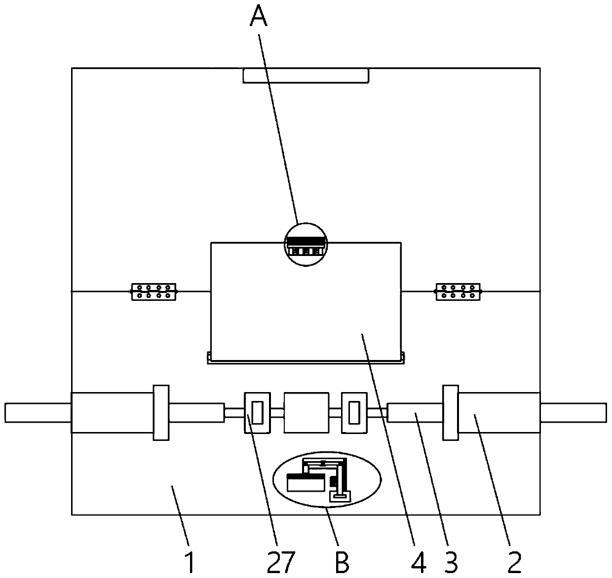
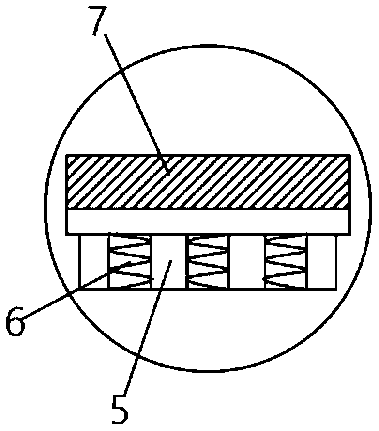
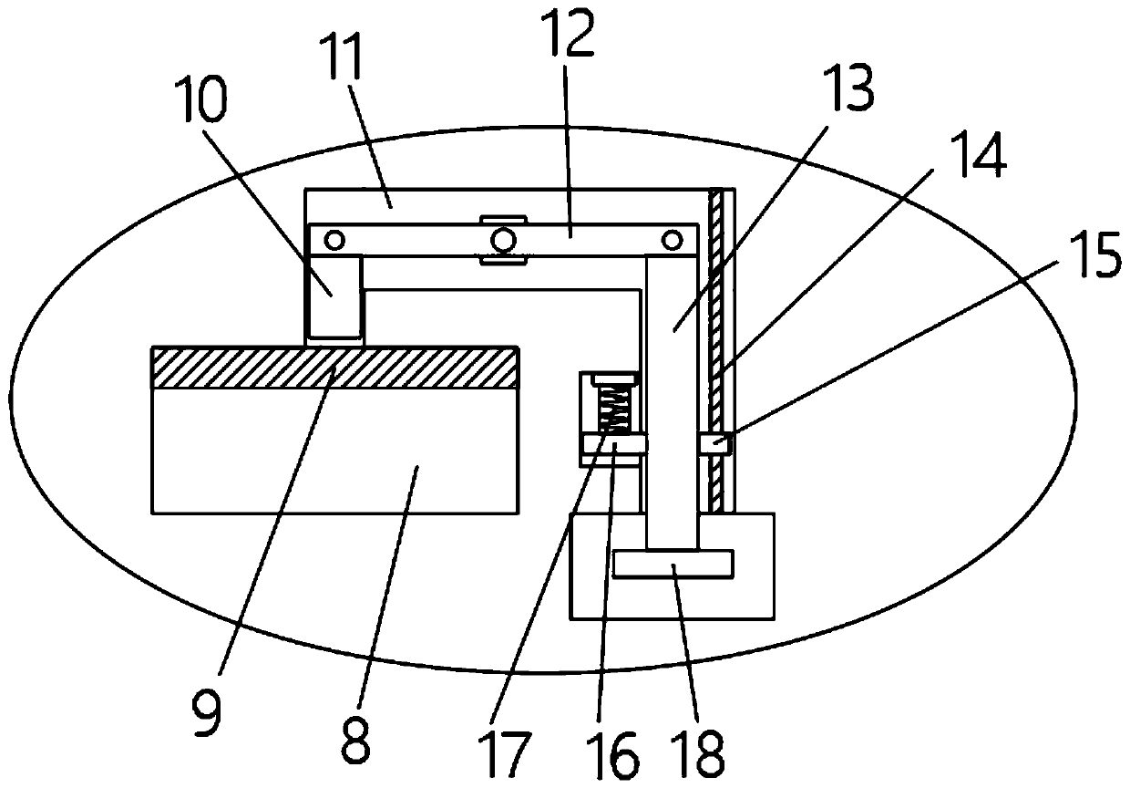
The invention discloses an optical cable fixing device for an optical cable fusion splicing box, which comprises a box body and an optical cable. Sleeves are symmetrically installed on both sides of the middle part of the box body, and the optical cable passes through the sleeves at both ends. The box body The upper end of the cover is rotatably connected with a cover, the middle part of the top of the cover is equipped with a spring block, the bottom of the box body is provided with a first slot at the position corresponding to the spring block, and the top of the first slot is A buckle is provided horizontally, a groove is provided on the upper end of the first card slot, and the groove communicates with the first card slot, a first connecting rod is horizontally provided in the groove, and the left end of the first connecting rod A block is rotatably connected, and the right end of the first connecting rod is rotatably connected with a second connecting rod. The invention has a stable and simple structure, is easy to install, has a one-button fixed structure, is easy to operate, and has a stable engagement, prevents the optical cable from being accidentally pulled, and can save a lot of time and energy for the optical cable welding workers, and is worth popularizing.

Description

technical field [0001] The invention relates to the technical field of optical cable processing and fixing devices, in particular to an optical cable fixing device for an optical cable fusion splice box. Background technique [0002] Optical cable fusion splice box or also known as optical cable splice box or splice box is a common device in optical cable communication, which is used to splice and connect optical cables. Since the fixing of the optical cable in the splice box will directly affect the reliability of communication, the ability of the splice box to fix the optical cable is an important indicator for evaluating the performance of the splice box. [0003] In the prior art, there are mainly two structures related to the fixing of optical cables in the splice box: in one type, it adopts a hoop / tie and an additional tie, wherein the hoop or tie is used to secure the The optical cable is tightly held on the end of the optical cable fixing frame opposite to the cable...

Claims


Application Information

Patent Timeline
Patent Type & Authority Patents(China)
IPC IPC(8): G02B6/255G02B6/44
CPCG02B6/255G02B6/4439
Inventor 王卫东余文辉张劲松
Owner NINGBO ZHANTONG TELECOM EQUIP INDAL
Learn More