
Optical Proximity Correction Method

An optical proximity correction and algorithm technology, applied in optics, opto-mechanical equipment, microlithography exposure equipment, etc., can solve problems such as slow calculation, and achieve the effect of avoiding iteration

Active Publication Date: 2020-04-24
SHANGHAI INTEGRATED CIRCUIT RES & DEV CENT
View PDF5 Cites 0 Cited by
  • Summary
  • Abstract
  • Description
  • Claims
  • Application Information

AI Technical Summary

Problems solved by technology

[0003] To solve this problem, there are some OPC algorithms that consider the interactions between multiple fragments, but such OPC algorithms are often computationally slow because the interaction matrix between each fragment must be updated every iteration
In addition, although the OPC solutions derived from these OPC algorithms are also tolerant to edge position error (EPE), they may not be optimal from the perspective of lithography process window

Method used


Image

  • Optical Proximity Correction Method
  • Optical Proximity Correction Method
  • Optical Proximity Correction Method

Examples


Embodiment Construction

[0038] Example embodiments will now be described more fully with reference to the accompanying drawings. Example embodiments may, however, be embodied in many forms and should not be construed as limited to the examples set forth herein; rather, these embodiments are provided so that this disclosure will be thorough and complete and will fully convey the concept of example embodiments to those skilled in the art. The described features, structures, or characteristics may be combined in any suitable manner in one or more embodiments.

[0039]Furthermore, the drawings are merely schematic illustrations of the present disclosure and are not necessarily drawn to scale. The same reference numerals in the drawings denote the same or similar parts, and thus repeated descriptions thereof will be omitted. Some of the block diagrams shown in the drawings are functional entities and do not necessarily correspond to physically or logically separate entities. These functional entities m...


PUM


Abstract

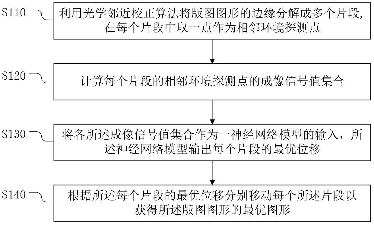
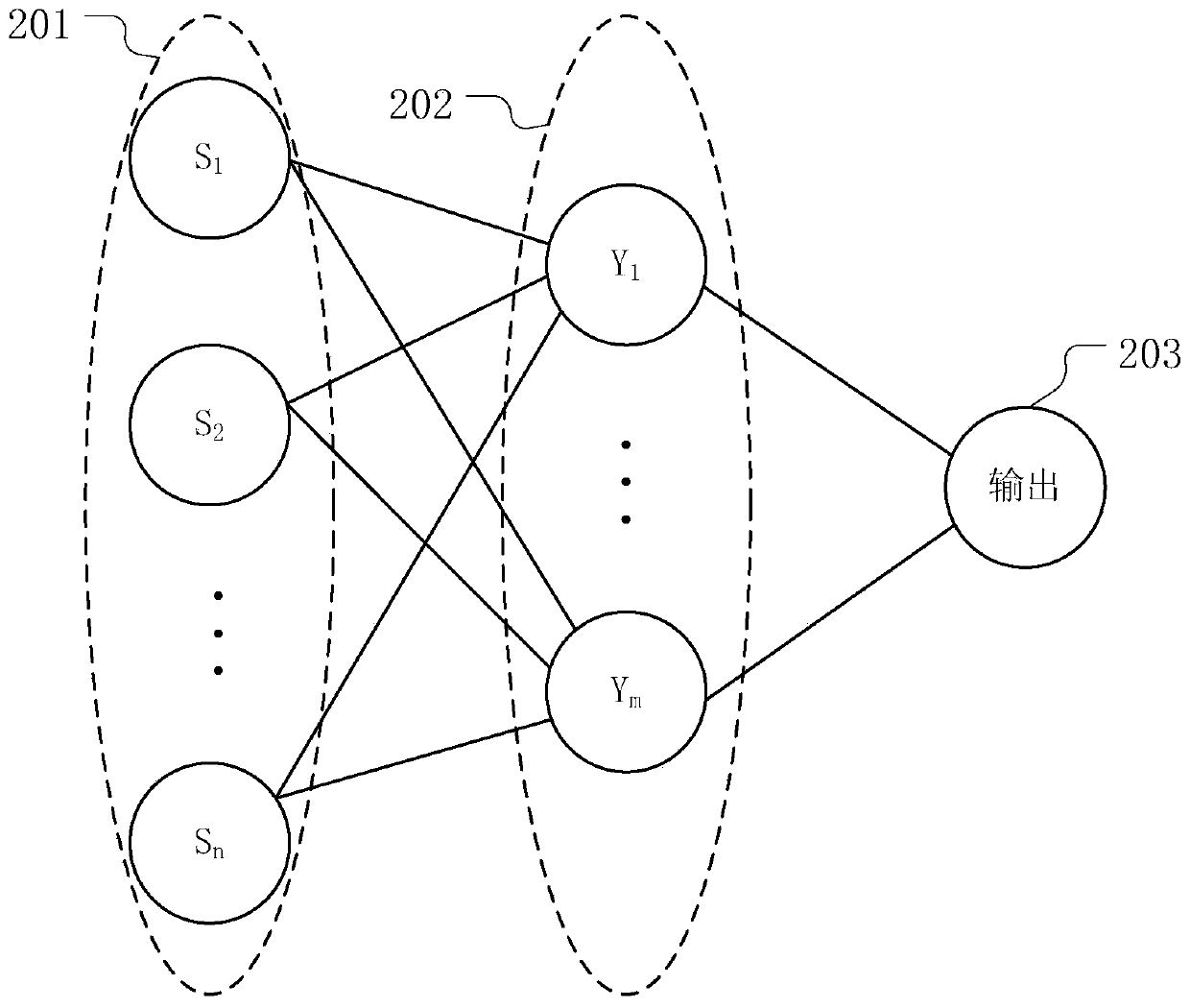
The invention provides an optical proximity correction method. The optical proximity correction method comprises the steps of dividing a layout pattern edge into multiple fragments according to an optical proximity correction algorithm, and taking one point in each fragment as an adjacent environment detection point; calculating an imaging signal value set {S<1>, S<2>, S<3> until S<n>} of the adjacent environment detection point of each fragment, wherein n is a positive integer; taking each imaging signal value set {S<1>, S<2>, S<3> until S<n>} as the input of a neural network model, wherein the neural network model outputs the optimal displacement (<delta>X and <delta>Y) of each fragment; and moving each fragment according to the optimal displacement (<delta>X and <delta>Y) of each fragment to obtain the optimal pattern of the layout pattern. By virtue of the optical proximity correction method provided by the invention, the optimal pattern of the layout pattern can be obtained.

Description

technical field [0001] The invention relates to the technical field of semiconductors, in particular to an optical proximity correction method. Background technique [0002] Optical proximity correction (OPC) is a technique commonly used in semiconductor chip manufacturing. Optical Proximity Correction (OPC) is to correct the pattern of the mask template to solve the problem of deformation of the photolithography pattern as much as possible. The traditional OPC algorithm only considers the error of each segment of the mask pattern in the correction process to determine the modification amount of each step, without considering the interaction between adjacent segments of the mask pattern. This algorithm is used in advanced lithography Under the strong spatial coherence imaging light illumination condition, the convergence speed is slow, or even unable to converge. At present, in the 14nm, 10nm, and 7nm node lithography processes, the imaging light illumination obtained from...

Claims


Application Information

Patent Timeline
Patent Type & Authority Patents(China)
IPC IPC(8): G03F7/20G03F1/36
CPCG03F1/36G03F7/70441G03F7/70508
Inventor 时雪龙赵宇航陈寿面李铭
Owner SHANGHAI INTEGRATED CIRCUIT RES & DEV CENT
Learn More