Electric connector for circuit substrate

A technology for circuit substrates and electrical connectors, which is applied to circuits, connections, and components of connecting devices, etc., can solve the problems of difficulty in ensuring the strength of contact pressure, lack of contact pressure, thinning, etc., to ensure the amount of elastic displacement. , to maintain the effect of high strength

Active Publication Date: 2018-03-13
HIROSE ELECTRIC GROUP
View PDF9 Cites 3 Cited by
  • Summary
  • Abstract
  • Description
  • Claims
  • Application Information

AI Technical Summary

Problems solved by technology

However, if a sufficient amount of elastic displacement is to be ensured, the terminal, including the elastic contact portion, becomes thinner and thinner. As a result, the elastic contact portion becomes too soft and cannot obtain sufficient contact pressure.
[0011] In addition, according to Patent Document 1, it is described that terminals can also be held by the movable case and the fixed case by integral molding. However, in this connector, the terminals are bent in the direction of thickness. Terminals, but even if it is a punched terminal punched along the thickness direction, when the terminal width is reduced for the purpose of arranging terminals at high-density pitches, although it can be held by integral molding, if you want to use The contact part of the terminal is in the form of elastic displacement. Since the terminal width is small, it is difficult to ensure the strength enough to withstand the contact pressure with the mating connector during elastic displacement.

Method used


Image

  • Electric connector for circuit substrate
  • Electric connector for circuit substrate
  • Electric connector for circuit substrate

Examples


Embodiment Construction

[0029] Embodiments of the present invention will be described below based on the drawings.

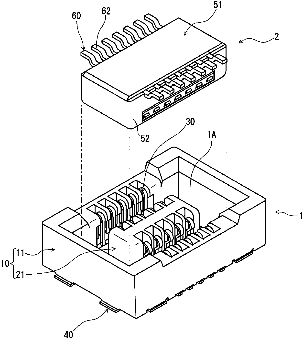
[0030] figure 1 It is a perspective view showing the external appearance of the receptacle connector 1 which is the electrical connector for circuit boards of this embodiment, and the plug connector 2 mated and connected thereto before mating connection.

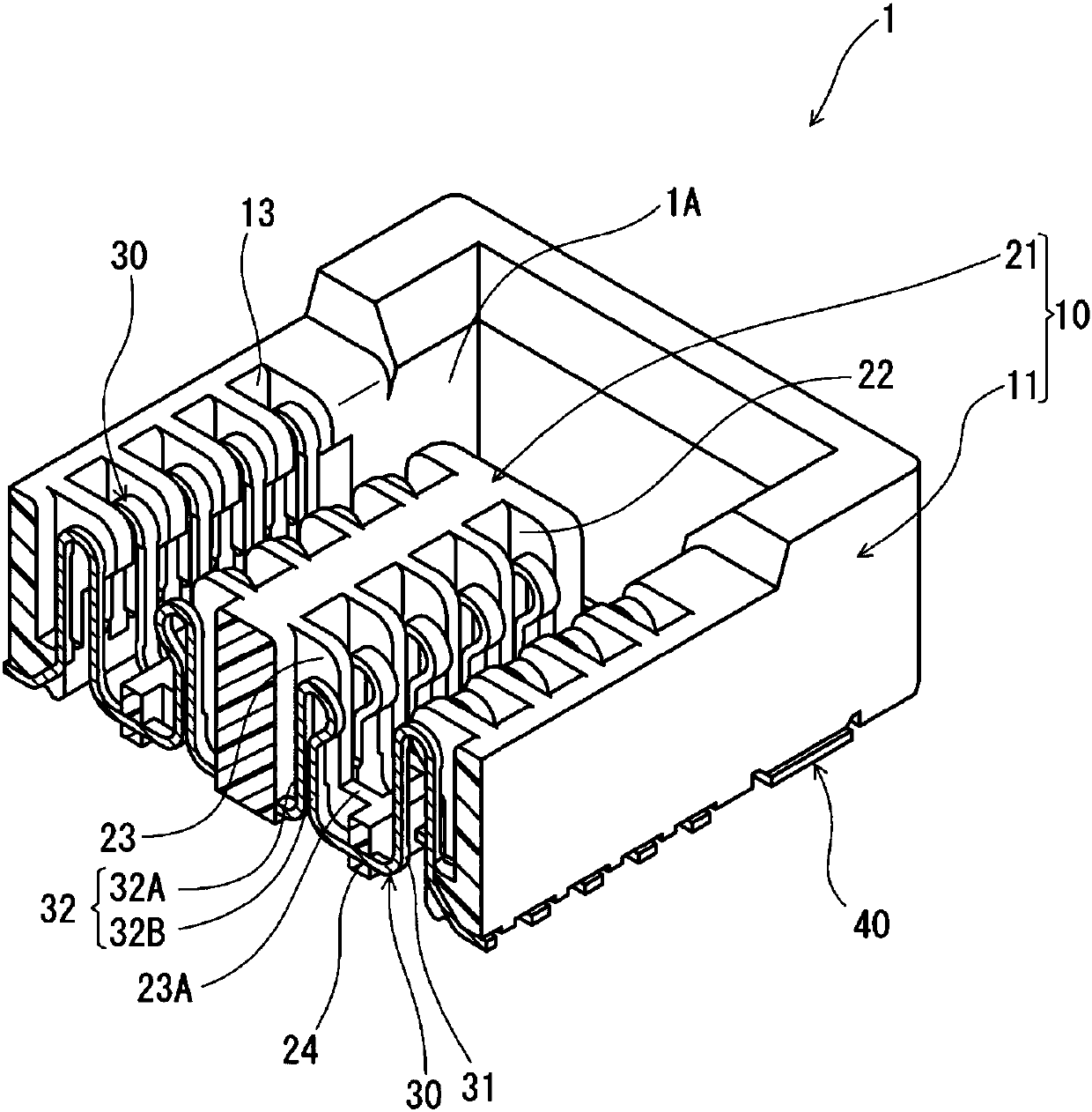
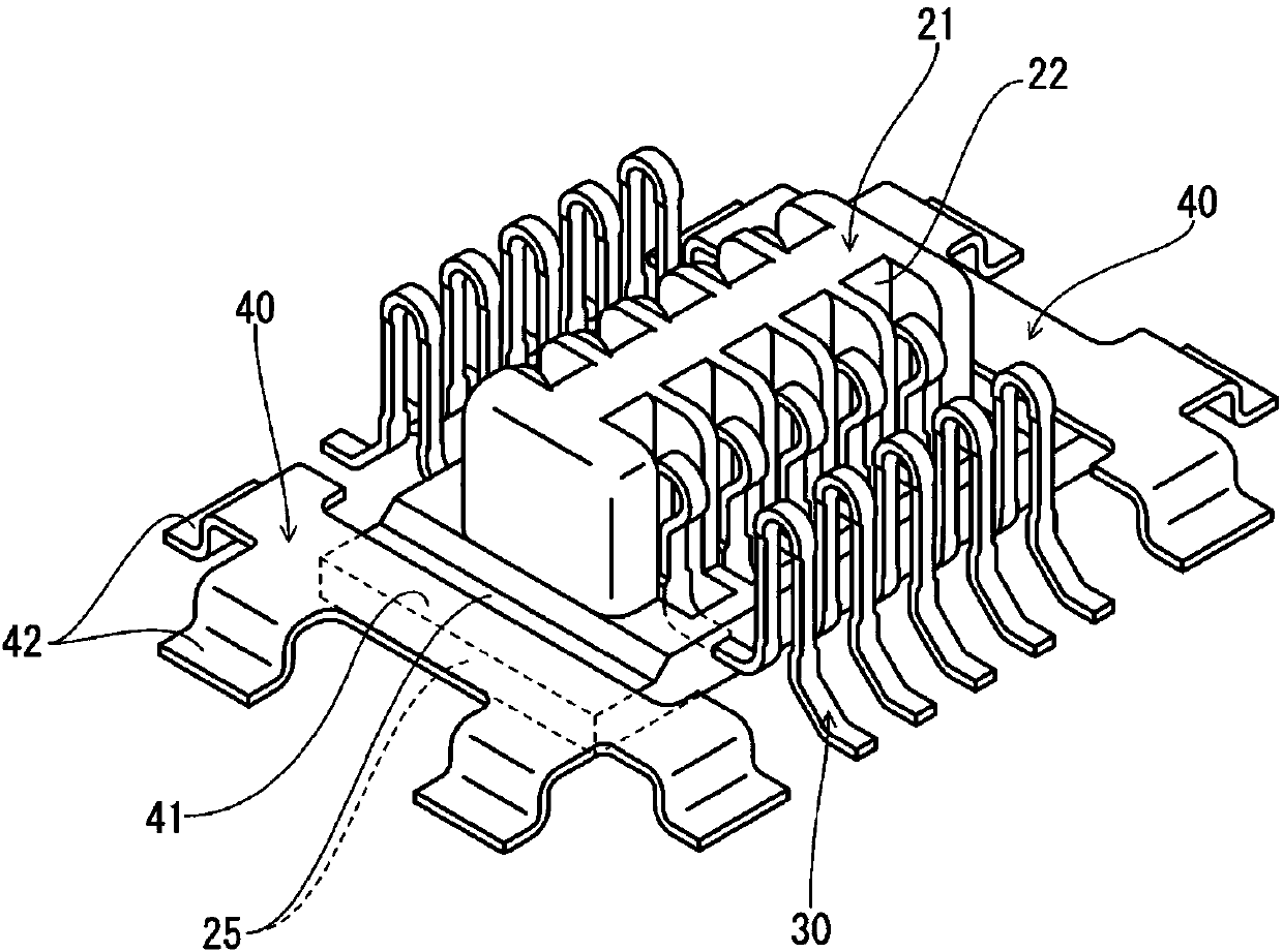
[0031] exist figure 1 Among them, the receptacle connector 1 has a receptacle housing 10 made of an electrically insulating material, a terminal 30 made of a metal plate held by the receptacle housing 10 , and a restricting metal fitting 40 .

[0032] The receptacle housing 10 has: a fixed housing 11 having a substantially rectangular frame-like planar shape viewed from above when the receptacle connector 1 is disposed on a circuit board (not shown); and a separate body from the fixed housing 11. The movable housing 21 is formed and located in the rectangular frame space of the above-mentioned fixed housing 11 . The space betwee...


PUM


Abstract

An object of the present invention is to provide an electric connector for a circuit substrate which can be brought into contact with a terminal of an object connector with sufficient contact pressure. The terminal (30) has a fixed side held part (34) held by a fixed housing, a movable side held part (36) held by a movable housing, and an intermediate elastic part (31) located between the fixed side held part and the movable side held part, the terminal also has an end part extending from the fixed side held part and located outside the fixed housing, a connecting part (35) connected to the circuit substrate, and a contact arm part (33) which is movably accommodated in a groove part formed in the movable housing at the other end side position of the terminal close to the fixed side held part, the contact arm part (33) has two elastic arm parts (32A, 32B) connected by a contact part, the movable side held part is formed at the base of each of the two arm parts, the fixed side held partis held by the fixed housing (11), and the movable side held part is held by the movable housing (21).

Description

technical field [0001] The invention relates to an electrical connector for a circuit substrate. Background technique [0002] In such a connector, when the mating direction of the connector is connected to the mating connector in the direction perpendicular to the surface of the circuit board, the mating connector may deviate from the standard position in the direction parallel to the surface of the circuit board. Therefore, a so-called floating connector capable of absorbing the above deviation is widely used, as disclosed in Patent Document 1, for example. [0003] The floating connector of Patent Document 1 has: a fixed housing (housing main body) which has a rectangular frame shape and is fixed to a circuit board at its bottom; and a plurality of terminals (contacts) arranged in a state of being bridged between the movable case and the above-mentioned fixed case. The fixed case is connected to the circuit board by soldering through the connecting portion of the termin...

Claims


Application Information

Patent Timeline
Patent Type & Authority Applications(China)
IPC IPC(8): H01R12/71H01R13/02H01R13/631
CPCH01R12/716H01R13/02H01R13/6315H01R13/24H01R13/639H01R13/64
Inventor 小林勇贵
Owner HIROSE ELECTRIC GROUP
Why Eureka
Try Eureka