
DIN type interface laser device

A laser and interface technology, which is applied in lasers, laser components, laser optical equipment, etc., can solve problems such as low pass rate, large optical signal attenuation, poor alignment between ceramic core and connector, and achieve reasonable size design and reduce Effect of Lateral Offset and Angular Deviation

Inactive Publication Date: 2018-03-13
THE 44TH INST OF CHINA ELECTRONICS TECH GROUP CORP
View PDF5 Cites 2 Cited by
  • Summary
  • Abstract
  • Description
  • Claims
  • Application Information

AI Technical Summary

Problems solved by technology

[0003] At the beginning of the design, considering the convenience of insertion, the inner diameter of the limiting cavity was designed to be 2.6mm (the outer diameter of the ceramic core and the insertion part were both 2.5mm), and the axial length of the positioning tube was designed to be 5mm; trial production During the process, it was found that the pass rate of the sample was low, and the reason for the low pass rate was mainly that the alignment between the ceramic core and the connector was poor, resulting in a large attenuation of the optical signal output by the post-transmission optical fiber.

Method used


Image

  • DIN type interface laser device
  • DIN type interface laser device

Examples


Embodiment Construction

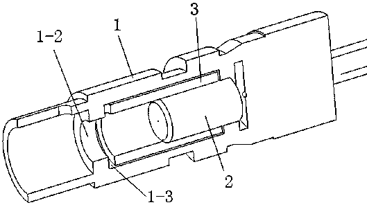
[0013] A DIN-type interface laser, the DIN-type interface laser includes a housing 1, a ceramic core 2, a positioning tube 3 and a TO laser; the inner hole of the housing 1 forms a plug-in section, a connecting section and a Installation section; the left end of the plug-in section communicates with the external environment, and the middle part of the plug-in section is provided with an annular protrusion. The space on the right side of the limiting chamber 1-2 is recorded as the installation chamber 1-3; the left end of the connecting section communicates with the right end of the installation chamber 1-3, the right end of the connecting section communicates with the installation section, and the middle part of the connecting section is provided with a stepped surface , the connecting section on the left side of the step surface forms a plug-in cavity, the connecting section on the right side of the step surface forms a light-guiding cavity, and the inner diameter of the plug-...


PUM


Abstract

The invention discloses a DIN type interface laser device. An optimal design is carried out on the structure parameters of the DIN type interface laser device through a simulation experiment. The DINtype interface laser device has the beneficial effects that according to the disclosed DIN type interface laser device, the dimensional design of the DIN type interface laser device is more reasonable, the lateral deviation and angular deviation of an inserting part and a ceramic core can be effectively reduced, and an optical signal output by the DINA type interface laser device can be conductedoutside in a low-attenuation manner.

Description

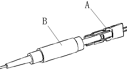
technical field [0001] The invention relates to an interface laser technology, in particular to a DIN type interface laser. Background technique [0002] In order to meet the needs of customers, our institute has newly designed an interface laser. The connection between the interface laser and the subsequent transmission fiber adopts the DIN interface connection method, so it is called the DIN interface laser; the DIN interface laser mainly includes Shell, ceramic core, positioning tube and TO laser; the role of the ceramic core is to guide the output light of the TO laser, and the positioning tube and the limiting cavity in the shell are used to insert and guide the connector on the subsequent transmission fiber and positioning for easy use, and also enables precise alignment of the ceramic core and the connector (the optical fiber is integrated in the ceramic core, the end of the post-transmission fiber is set in the socket on the connector, and the ceramic core is aligned...

Claims


Application Information

Patent Timeline
Patent Type & Authority Applications(China)
IPC IPC(8): H01S3/00
CPCH01S3/005
Inventor 陈俊宇丁鹏陈春霞王长福胡俊豪李欢吴广詹萍萍
Owner THE 44TH INST OF CHINA ELECTRONICS TECH GROUP CORP
Learn More