Optical Path Alignment Method for Inspection of Convex Aspheric Mirror

An aspheric and reflective mirror technology, applied in the field of optical detection, can solve the problem of inability to meet the high-precision detection of convex aspheric mirrors, and achieve the effect of improving production efficiency

Active Publication Date: 2019-08-23
CHANGGUANG SATELLITE TECH CO LTD
View PDF7 Cites 0 Cited by
  • Summary
  • Abstract
  • Description
  • Claims
  • Application Information

AI Technical Summary

Problems solved by technology

[0005] Based on this, it is necessary to align the optical paths of the interferometer, Handel sphere and the mirror to be inspected only by visual inspection in the prior art, resulting in a certain inclination and eccentricity between the three, which cannot meet the requirements of non-convex and non-convex alignment. The problem of high-precision detection of the surface shape and effective area of ​​spherical mirrors provides an optical path alignment method for the detection of convex aspheric mirrors

Method used


Image

  • Optical Path Alignment Method for Inspection of Convex Aspheric Mirror
  • Optical Path Alignment Method for Inspection of Convex Aspheric Mirror
  • Optical Path Alignment Method for Inspection of Convex Aspheric Mirror

Examples


Embodiment Construction

[0024] The technical solutions of the present invention will be described in detail below in conjunction with the accompanying drawings and preferred embodiments.

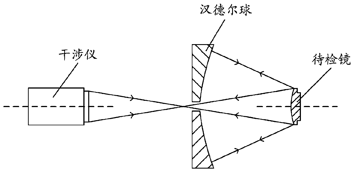
[0025] Such as figure 1 Shown is the schematic diagram of the aberration-free point detection method using the Handel sphere. The standard spherical wave emitted by the interferometer through the standard mirror is reflected to the Handel sphere by the mirror to be inspected. Based on the characteristics of the aberration-free point, the Handel sphere reflects the incident The light is reflected by the mirror to be inspected, and finally reflected back to the interferometer through the standard mirror, so as to realize the detection of the surface shape of the mirror to be inspected and the size and shape of the effective area. For a system that uses Handel spheres to detect convex aspheric mirrors, accurately controlling the relative positional relationship among the interferometer standard mirror, Handel spheres,...


PUM


Abstract

The invention relates to a light path alignment method for convex aspheric surface reflector detection and belongs to the technical field of optical detection. The method is characterized by realizingcoarse alignment between an interferometer and a Handel ball by utilizing a scale mark device fixed at the back face of the Handel ball; realizing perfect alignment between the interferometer and theHandel ball by utilizing a cat eye image of an interferometer spherical standard mirror; and after finishing light path alignment between the interferometer and the Handel ball, carrying data processing on a surface interference image of a convex aspheric surface reflector to be detected collected by the interferometer, and determining whether light path alignment between the Handel ball and theconvex aspheric surface reflector to be detected is realized by judging whether an outer circle data center and an inner hole data center of the surface interference image obtained after data processing are overlapped, thereby solving the problem of alignment between the convex aspheric surface reflector to be detected and the whole optical detection system in the process of adopting the Handel ball to carry out convex aspheric surface reflector detection.

Description

technical field [0001] The invention relates to the technical field of optical detection, in particular to an optical path alignment method for detection of convex aspheric mirrors. Background technique [0002] For the mirror of the coaxial structure aerospace camera, the convex aspheric mirror is usually used as the secondary mirror of the camera. The surface shape accuracy, the size and shape of the effective area of ​​the convex aspheric mirror are directly related to the final imaging quality of the aerospace camera. and area, so the high-precision detection of the surface shape and effective area of ​​the convex aspheric mirror is of great significance to the entire aerial camera. [0003] For the detection of the surface shape and effective area of ​​a convex aspheric mirror, the following two methods are usually used: the first is to use the optical compensation method, using a transmission compensator or a computer generated hologram (Computer GeneratedHologram, CGH...

Claims


Application Information

Patent Timeline
Patent Type & Authority Patents(China)
IPC IPC(8): G01B9/02
Inventor 王兴武志勇王高文李冰琳
Owner CHANGGUANG SATELLITE TECH CO LTD
Why Eureka
Try Eureka