Tool clamping mechanism and method for double-sided turning of thin-walled and equal-thickness parts

A clamping mechanism and tool technology, applied in the direction of tool clamps, etc., can solve the problems of restricting the mass production of parts, uneven wall thickness of parts, thickness dimensions, parallelism and flatness easily out of tolerance, etc., to achieve the improvement of processing efficiency. Effect

Active Publication Date: 2019-03-05
SHENYANG LIMING AERO-ENGINE GROUP CORPORATION
View PDF5 Cites 0 Cited by
  • Summary
  • Abstract
  • Description
  • Claims
  • Application Information

AI Technical Summary

Problems solved by technology

Even so, the gap cannot be completely eliminated, and the suspended point still exists. In this state, the turning part will spring back after processing due to the elastic deformation of the suspended part, resulting in uneven wall thickness of the part, and the upper and lower end surfaces The parallelism and flatness are also difficult to meet the processing requirements
[0004] Due to the constraints of the existing processing methods, the part is easily out of tolerance in terms of thickness, parallelism and flatness, so that the processing pass rate of the part is only about 10%, which seriously limits the mass production of parts

Method used


Image

  • Tool clamping mechanism and method for double-sided turning of thin-walled and equal-thickness parts
  • Tool clamping mechanism and method for double-sided turning of thin-walled and equal-thickness parts
  • Tool clamping mechanism and method for double-sided turning of thin-walled and equal-thickness parts

Examples


Embodiment Construction

[0024] The present invention will be further described in detail below in conjunction with the accompanying drawings and specific embodiments.

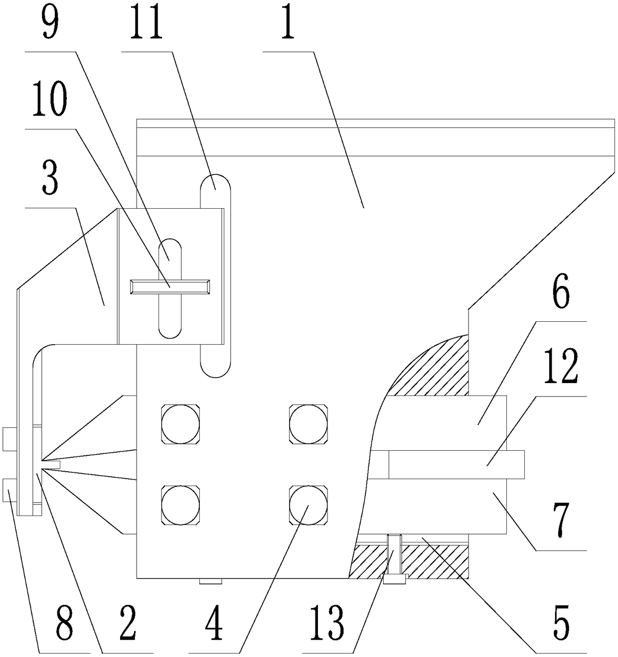
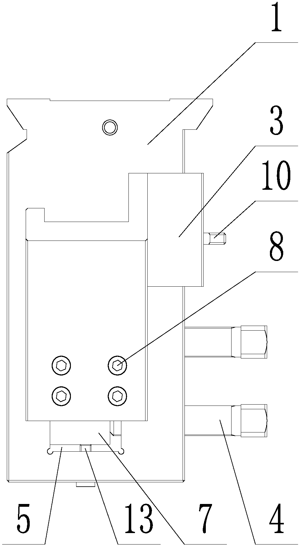
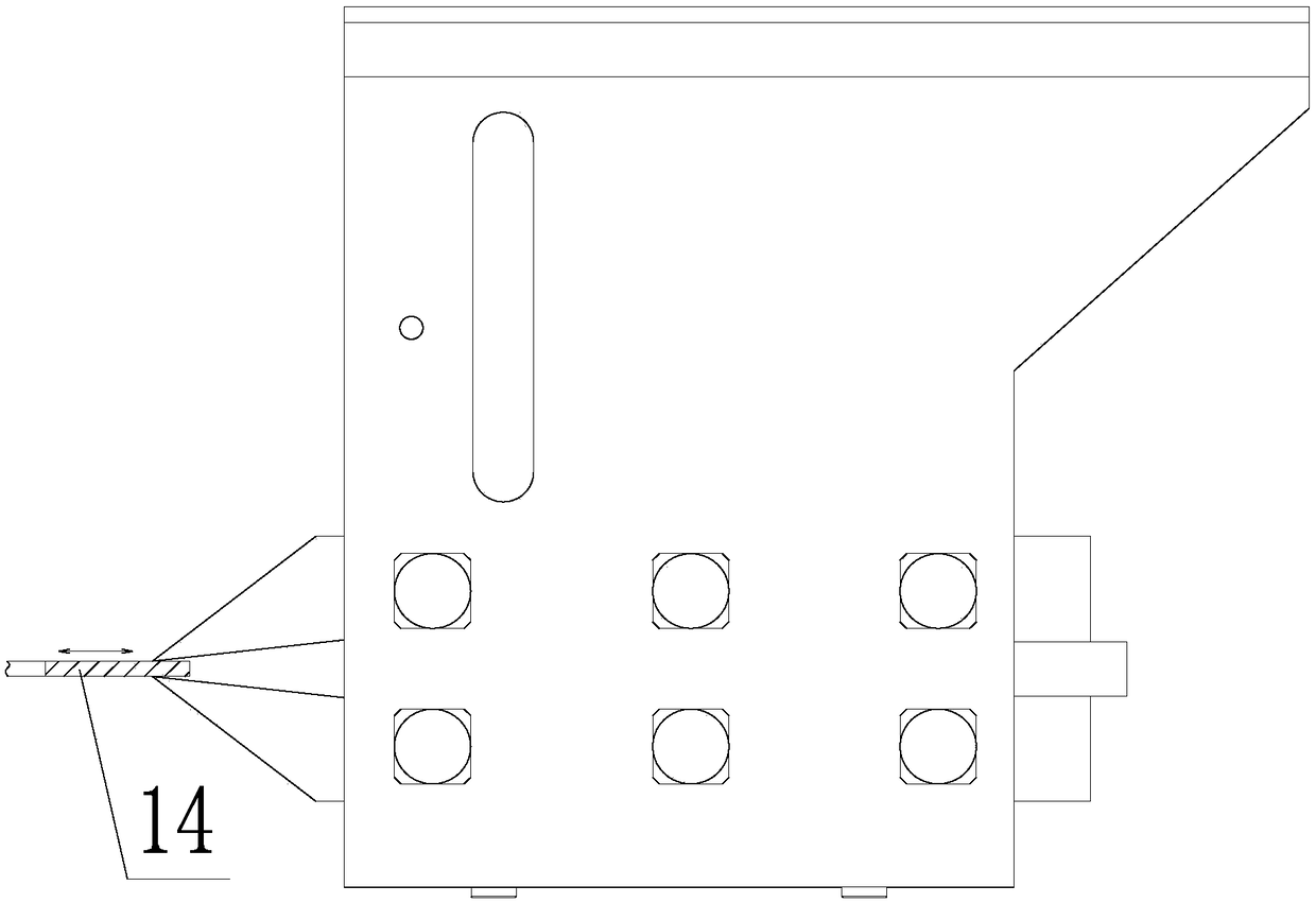
[0025] Such as figure 1 , 2 As shown, a tool clamping mechanism for double-sided turning of thin-walled and thick parts includes a tool holder body 1, a tool setting block 2, a tool setting block mounting frame 3 and a tool fastening bolt 4; the tool holder body 1 The top adopts a dovetail slide rail structure, and the tool holder main body 1 is connected with the machine tool holder through the top dovetail slide rail structure; a tool mounting hole 5 is opened at the lower part of the tool holder main body 1, and a The upper and lower turning tools are divided into an upper turning tool 6 and a lower turning tool 7. The upper turning tool 6 and the lower turning tool 7 are arranged in parallel and the tool tips are facing each other; Two rows of tool fastening bolts 4 are distributed, the upper row of tool fastening bolts 4 cooper...


PUM


Abstract

Disclosed is a double-sided turning cutting tool clamping mechanism and method for thin-wall uniform-thickness parts. A tool clamping main body of the double-sided turning cutting tool clamping mechanism is connected with a machine tool cutter frame. A cutting tool installing hole is formed in the lower part of the tool clamping main body. Upper turning tools and lower turning tools in the cuttingtool installing hole are installed parallelly and tool noses of each upper turning tool and the corresponding lower turning tool are opposite. The upper turning tools and the lower turning tools arefixed through tool fastening bolts. The upper part of a feeler block installing frame is connected with the tool clamping main body and a feeler block is fixedly installed at the lower part of the feeler block installing frame. Turning tool separation distance adjusting cushion blocks are installed between the upper turning tools and the lower turning tools. The tool clamping main body below the lower turning tools is provided with a tool height trimming bolt. The double-sided turning method includes the steps that the tool clamping main body is connected with the machine tool cutter frame; the feeler block is installed; the lower turning tools are installed to make the tool noses of the lower turning tools abut against tool setting points; the upper turning tools are installed and the turning tool separation distance adjusting cushion blocks are placed between the upper turning tools and the lower turning tools to make the tool noses of the upper turning tools abut against tool setting points; the tool fastening bolts are tightened; the feeler block installing frame and the feeler block on the feeler block installing frame are dismounted; and a turning-lathe is started to conductsynchronous turning of the upper and lower end surfaces of the parts.

Description

technical field [0001] The invention belongs to the technical field of aero-engine component manufacturing, and in particular relates to a tool clamping mechanism and method for double-sided turning of thin-walled and other thick parts. Background technique [0002] Taking a four-stage rotating ring part as an example, it is a thin-walled and equal-thickness part. The wall thickness is required to be 2.5±0.05mm, and the parallelism between the upper and lower end surfaces of the part is required to be 0.05mm. [0003] At present, the upper and lower end surfaces of this part can only be processed by multiple flipping and turning. Since the incoming material of the part is sheet material, and in the free state, the flatness of the upper and lower end surfaces of the part is about 0.5mm. In order to ensure the fit between the part and the reference block and prevent the part from being suspended, it is necessary to pad the feeler gauge on the suspended part. Even so, the gap ...

Claims


Application Information

Patent Timeline
Patent Type & Authority Patents(China)
IPC IPC(8): B23B29/26
CPCB23B29/26
Inventor 朱颖张洪刚纪鑫侯波韩洪征
Owner SHENYANG LIMING AERO-ENGINE GROUP CORPORATION
Why Eureka
Try Eureka