Supercharge Your Innovation With Domain-Expert AI Agents!

Protective cover for a lathe

A protective cover and lathe technology, which is applied in the direction of maintenance and safety accessories, metal processing equipment, metal processing machinery parts, etc., can solve the problem of inability to adjust the height of the protective cover of the lathe, affect the sanitary environment of the protective cover of the lathe, and cannot clean the protective cover of the lathe Dirt and other problems, to achieve the effect of favorable operation, practical function and simple structure

Active Publication Date: 2019-09-13
沙迪克南通机电科技有限公司
View PDF5 Cites 0 Cited by
  • Summary
  • Abstract
  • Description
  • Claims
  • Application Information

AI Technical Summary

Problems solved by technology

[0004] The present invention provides a protective cover for lathes, which can effectively solve the above-mentioned problems in the background technology that there is no first hydraulic lifting rod, the height of the lathe protective cover body cannot be adjusted, it is inconvenient to install and disassemble, and there is no cleaning box and dust collection box. The dirt on the lathe protective cover body cannot be cleaned, and the dust on the lathe protective cover body cannot be removed, which affects the hygienic environment of the lathe protective cover body. There is no second hydraulic lifting rod and pulley, which cannot reduce the vibration generated when the machine tool is working, which affects the work. Efficiency, at the same time, the body of the protective cover of the lathe cannot be moved, which is inconvenient for the staff to operate and affects work efficiency

Method used


Image

  • Protective cover for a lathe
  • Protective cover for a lathe
  • Protective cover for a lathe

Examples


Embodiment

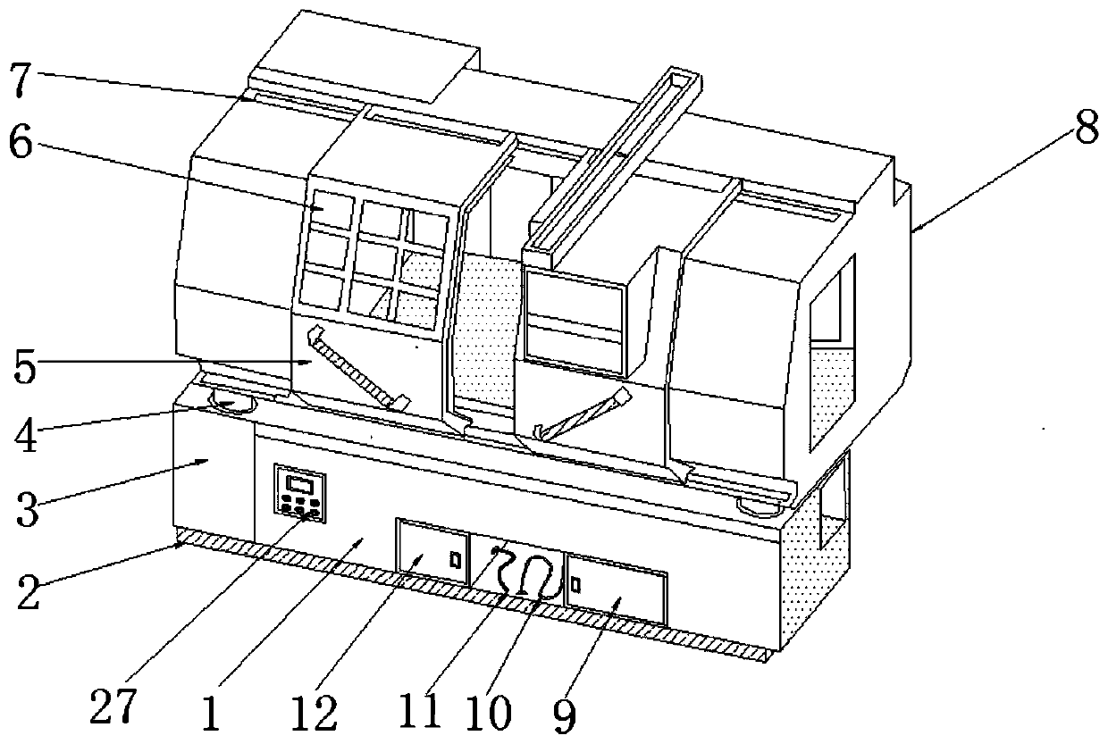
[0023] Example: such as Figure 1-5 As shown, the present invention provides a technical solution, a lathe protective cover, including a lathe protective cover body 1, a shock absorbing plate 2, a base 3, a first hydraulic lifting rod 4, a sliding door 5, an observation window 6, and a slide rail 7. Upper cover 8, dust collection box 9, dust suction port 10, nozzle 11, cleaning box 12, telescopic rod groove 13, handle 14, dust bag 15, filter screen 16, motor 17, air outlet 18, support rod 19, Fan blade 20, pressure frame 21, pulley 22, base plate 23, second hydraulic lifting rod 24, water tank 25, water pipe 26, control switch 27, fixed plate 28, water pump 29 and water inlet 30, lathe protective cover body 1 upper end setting There is an upper cover 8, and the lower end of the lathe protective cover body 1 is provided with a base 3, and the bottom end of the lathe protective cover body 1 is provided with a damping plate 2, and the lower end of the lathe protective cover body ...


PUM


Abstract

The invention discloses a protective cover for a lathe. The protective cover comprises a lathe protective cover body, a damping plate, first hydraulic lifting rods, a dust suction box, a cleaning boxand pulleys. The damping plate is arranged at the bottom end of the lathe protective cover body, the cleaning box is arranged at the position, close to one side of a control switch, of the front surface of a base, and the dust suction box is arranged at the position, close to one end of a dust suction opening, of the front surface of the base. The protective cover is scientific and reasonable in structure and safe and convenient to use; the first hydraulic lifting rods are arranged, the height of the lathe protective cover body can be adjusted at any time, and mounting and demounting of workers are convenient; the cleaning box and the dust suction box are arranged, dirt on the lathe protective cover body can be cleaned away conveniently, and dust on the lathe protective cover body can be cleared away; and a second hydraulic lifting rod and the pulleys are arranged, vibration generated during work of a machine tool can be relieved, and the lathe protective cover body can be moved at anytime. The protective cover is simple in structure, practical in function and convenient to mount and demount.

Description

technical field [0001] The invention relates to the technical field of protective covers for lathes, in particular to a protective cover for lathes. Background technique [0002] The machine tool protective cover is used to protect the guide rail of the machine tool. It can protect the internal hard guide rail, linear guide rail, ball screw or transmission rack of the machine tool from external corrosion and damage. There are many types, such as organ protective cover and steel plate protection. Cover, these two kinds are used on the guide rail, also have the leading screw protective cover used on the leading screw, also have rolling shutter protective cover and armor protective cover etc., the present invention is exactly the lathe protective cover that numerical control lathe is used. [0003] However, the protective covers for lathes currently on the market are not only complex in structure, but also have a single function. The first hydraulic lifting rod is not provided,...

Claims


Application Information

Patent Timeline
Patent Type & Authority Patents(China)
IPC IPC(8): B23Q11/08B23Q11/00
Inventor 不公告发明人
Owner 沙迪克南通机电科技有限公司
Features
  • R&D
  • Intellectual Property
  • Life Sciences
  • Materials
  • Tech Scout
  • Unparalleled Data Quality
  • Higher Quality Content
  • 60% Fewer Hallucinations
Learn More