
Method and arrangement for monitoring a brake system of a brake arrangement of a rail vehicle

A rail vehicle and braking system technology, applied in the field of braking systems and devices used to monitor the braking devices of rail vehicles, can solve the problems of unnecessary increase in wheel and track wear, and achieve the effect of small sandblasting equipment

Inactive Publication Date: 2018-03-20
SIEMENS MOBILITY GMBH
View PDF7 Cites 0 Cited by
  • Summary
  • Abstract
  • Description
  • Claims
  • Application Information

AI Technical Summary

Problems solved by technology

This has the result that, by activating the sand blasting device, the wear of the wheels and rails can be increased unnecessarily and sand can also be sprayed in the area of ​​the sensitive switch tongue
In addition, relatively bulky and expensive blasting equipment must be used

Method used


Image

  • Method and arrangement for monitoring a brake system of a brake arrangement of a rail vehicle
  • Method and arrangement for monitoring a brake system of a brake arrangement of a rail vehicle
  • Method and arrangement for monitoring a brake system of a brake arrangement of a rail vehicle

Examples


Embodiment Construction

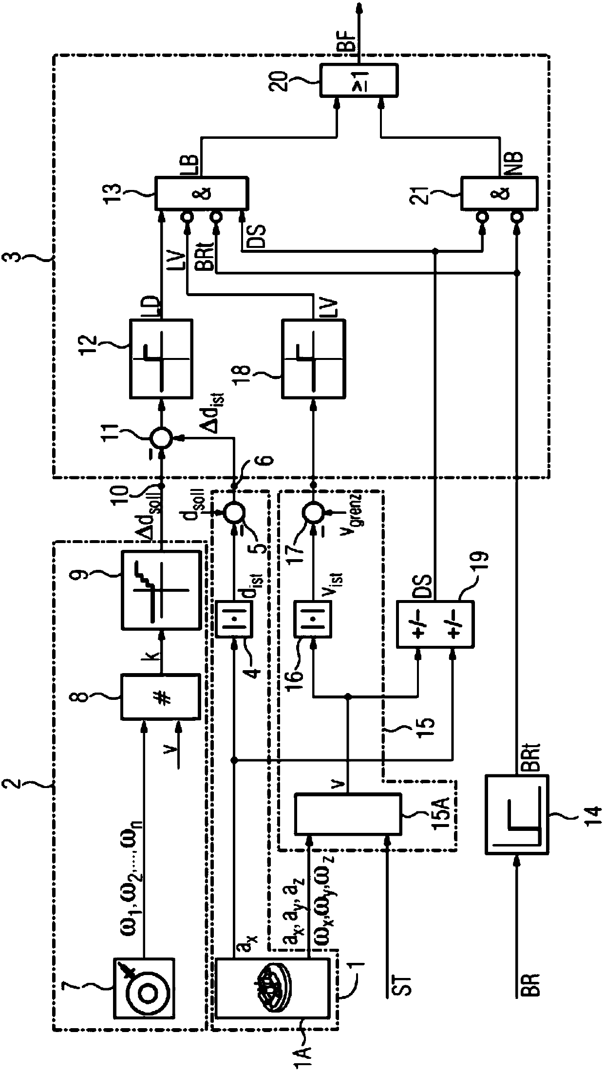
[0049] exist figure 1 The device for monitoring the braking system of the braking device of the rail vehicle shown in the not shown comprises as main components: a measuring mechanism 1 for detecting the deceleration of the rail vehicle; in the rail vehicle for detecting the wheels and Measuring device 2 for the force fit between the rails; and an evaluation device 3 which issues an error notification in the event of a slight deceleration of the rail vehicle compared to normal and a normal force fit between the wheels and the rail Signal BF.

[0050] Measuring device 1 contains an inertial sensor group 1A with an acceleration sensor (not shown in detail), which is parallel to the vehicle longitudinal axis of the rail vehicle. The deceleration actual value a is measured by means of the acceleration sensor of the inertial sensor group 1A x . An absolute value former 4 is connected to the inertial sensor group 1A or to its acceleration sensor, said absolute value former forms ...


PUM


Abstract

The invention relates to a method for monitoring a brake system of a brake arrangement with a plurality of brake systems of a rail vehicle. In order to be able to carry out such a method comparativelycost-effectively and gently for the wheel and rail, according to the invention the deceleration of the rail vehicle is detected with a deceleration measured variable (Deltadist) being obtained and the frictional connection between the wheel and rail is detected with a frictional connection measured variable (Deltadsoll) being obtained. In the event of a small deceleration measured variable (Deltadist) and a normal frictional connection measured variable (Deltadsoll), an error message signal (BF) is generated. In a brake system with at least one brake actuator, the deceleration of the rail vehicle is detected with a deceleration measured variable (Deltadist) being obtained and the brake force (f) of the at least one brake actuator is measured; in the case of a small deceleration measured variable (Deltadist) and a low brake force (f), an error message signal (BF) is generated.

Description

[0001] This application is a divisional application of a patent application with an application date of October 29, 2012, an application number of 201280064037.X, and an invention titled "Method and device for monitoring a braking system of a braking device of a rail vehicle". Background technique [0002] A braking device for a rail tractor with several braking systems is known from German patent document DE 195 10 755 C2. In this known braking device, the braking effect is monitored by detecting a deceleration in the braking situation and a deceleration signal is generated if the braking effect is too low. With the aid of the deceleration signal, measures are automatically triggered which make it possible to use all the braking systems present on the rail vehicle to bring about the greatest possible residual braking effect. Here, too, the sand blasting device (Sandstreuanlage) is activated in order to take into account the possible error case that a brake failure detected du...

Claims


Application Information

Patent Timeline
Patent Type & Authority Applications(China)
IPC IPC(8): B60T8/17B60T17/22B61H11/00
CPCB60T8/1705B60T17/228B61H11/00B61H11/005B60T2270/413B61L27/04G06F7/00G06F17/00G08G1/20
Inventor 维尔纳·布罗伊尔拉尔斯·勒文施泰因亚历山大·兰贝丘斯沃尔夫冈·鲁尔卡托尔斯滕·施蒂茨勒
Owner SIEMENS MOBILITY GMBH
Learn More