
Electronic candle

A technology for electronic candles and circuit boards, which is applied to electric light sources, circuit layouts, lighting devices, etc., can solve the problems of reduced assembly efficiency, easy to break wires, and circuit board de-soldering, etc., to facilitate manual assembly and avoid tearing. , the effect of small contact surface

Inactive Publication Date: 2018-03-20
舒自明
View PDF5 Cites 0 Cited by
  • Summary
  • Abstract
  • Description
  • Claims
  • Application Information

AI Technical Summary

Problems solved by technology

Since each wire of the coil is very thin, the protruding wire ends are in the form of filaments. During the process of manually assembling them to different positions on the mounting seat after being soldered to the circuit board, it is easy to tear the wire ends, resulting in breakage of the wire ends or desoldering from the circuit board. , such a design brings trouble to the manual assembly process, reduces the yield rate, and also reduces the assembly efficiency

Method used


Image

  • Electronic candle
  • Electronic candle
  • Electronic candle

Examples


Embodiment Construction

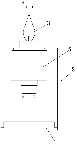
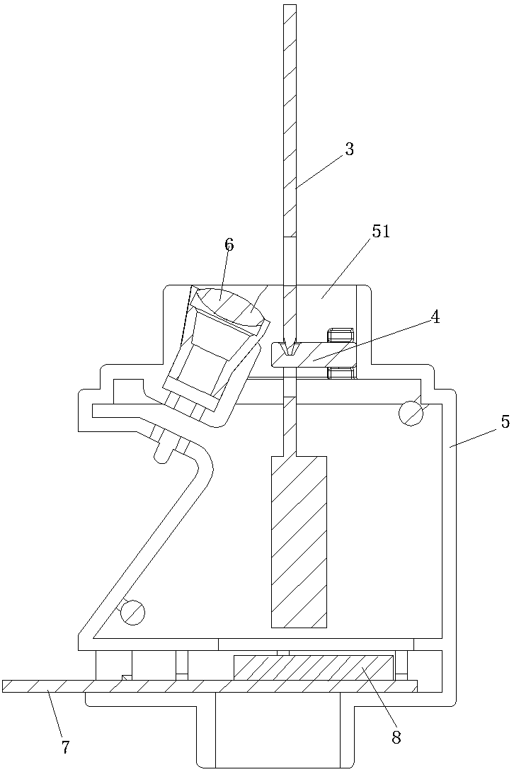
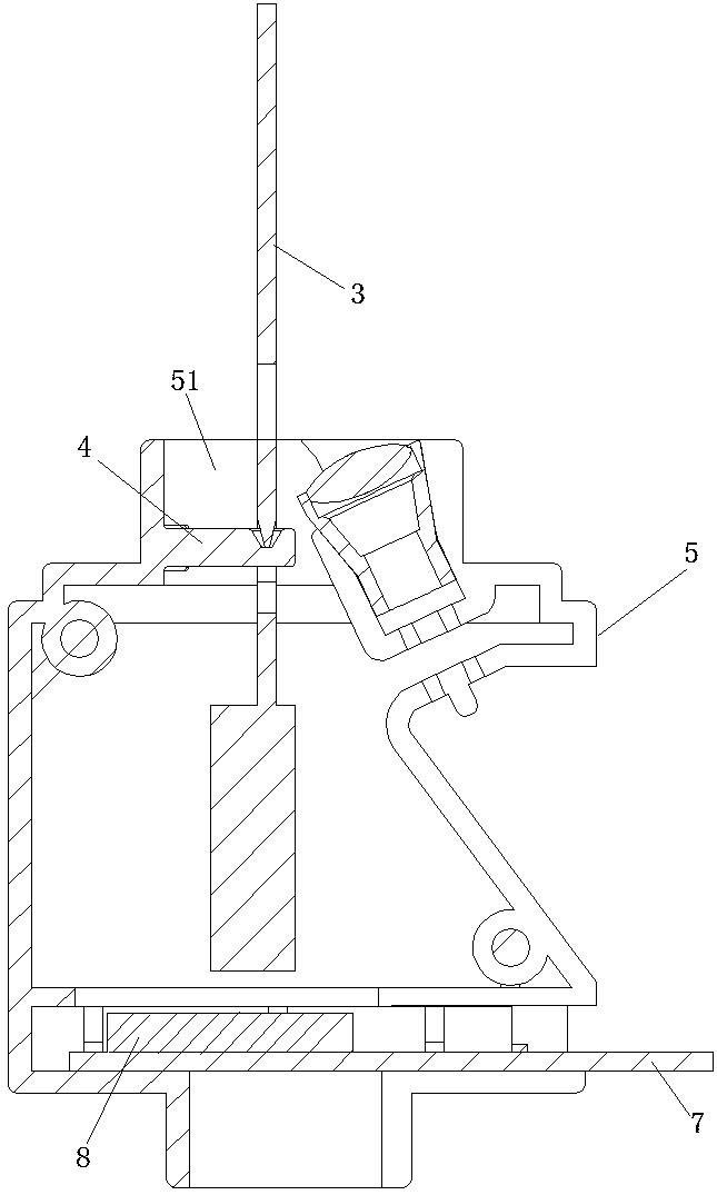
[0033] Such as Figure 1-9 As shown, an electronic candle includes a base 1, a hollow housing 2 installed on the base 1, a first through hole 21 arranged on the top of the housing 2, a flame sheet 3, a flame sheet support 4, and a A hollow mounting seat 5 in the inner cavity of the body 2, a light-emitting element 6 and a circuit board 7 installed on the mounting seat 5.

[0034] The top of the mounting base 5 is provided with a second through hole 51 , and the top of the mounting base 5 is assembled and fixed with the first through hole 21 . The lower part of the mounting base 5 is provided with a card slot 52 .

[0035] The flame sheet support 4 is integrally formed with the mounting seat 5 , and the flame sheet support 4 includes a horizontal cantilever seat 41 fixedly connected to the inner wall of the second through hole 51 . The front end of the cantilever seat 41 is provided with a groove 42, and the bottom of the groove 42 is a plane.

[0036] The flame sheet 3 incl...


PUM


Abstract

The invention discloses an electronic candle comprising a base, a shell, a first through hole, a flame piece, a flame piece support, a mounting seat, a light emitting piece and a circuit board. A second through hole is formed in the top of the mounting seat, the top of the mounting seat and the first through hole are assembled for fixing, the flame piece support and the mounting seat are integrally formed, and the flame piece support comprises a horizontal cantilever seat fixedly connected with the inner wall of the second through hole. A groove is formed in the front end of the cantilever seat, and the bottom of the groove is a plane. The flame piece comprises a flame body and a supporting part arranged at the lower end of the flame body, the supporting part is an inverted cone body, andthe lower end of the supporting part is shelved at the bottom of the groove. The flame body extends out of the second through hole and is higher than the top of the shell. A driving device for drivingthe flame piece to swing is arranged under the flame piece, and the light emitting piece is arranged on one side of the flame piece and can project light rays to the flame body. The flame piece support and the mounting seat are integrally formed, manual assembly is better facilitated, and swing of the flame piece is more flexible.

Description

technical field [0001] The invention specifically relates to an electronic candle. Background technique [0002] The existing electronic candle structure mainly includes a base, a housing, a flame sheet, a flame sheet support, a mount, a luminous part, a coil and a circuit board, and the flame sheet can swing to simulate the effect of a candle. The existing structure mainly has the following defects: [0003] 1. There are many small parts that make up the candle structure, and the flame sheet bracket is a single small part. When manually assembling, the flame sheet bracket needs to be assembled to the mounting seat first, and then the flame sheet can be hung on the flame sheet bracket. This During the process, due to the limited installation space in the mounting base, which is smaller than the size of a human finger, manual assembly is extremely inconvenient. The flame sheet often needs to be hung several times before it can be put in place, seriously affecting work effici...

Claims


Application Information

Patent Timeline
Patent Type & Authority Applications(China)
IPC IPC(8): F21S10/04F21V17/16F21V23/00F21Y115/10
CPCF21S10/046F21V17/164F21V23/00F21Y2115/10
Inventor 舒自明
Owner 舒自明
Learn More