Polarizer attachment equipment and system

A polarizer attachment and polarizer technology, applied in optics, nonlinear optics, instruments, etc., can solve the problems of affecting the quality of polarizer attachment, surface wear of the mechanism, affecting production capacity, etc., to optimize the attachment parameters and improve the corresponding ability, the effect of improving efficiency

Active Publication Date: 2018-03-20
WUHAN CHINA STAR OPTOELECTRONICS TECH CO LTD
View PDF12 Cites 3 Cited by
  • Summary
  • Abstract
  • Description
  • Claims
  • Application Information

AI Technical Summary

Problems solved by technology

[0003] At present, the traditional method of measuring and attaching the gap is to use a feeler gauge (thickness gauge) to measure, but there are two disadvantages as follows: First, the contact measurement is used, the measurement accuracy is not high, and there is a possibility of causing wear on the surface of the mechanism
During the measurement process of this method, the feeler gauge will be in contact with the attachment platform and the attachment roller. The attachment platform and the attachment roller are parts that require very high surface accuracy in the polarizer attachment equipment. There are wear and tear stickers when using the feeler gauge. The possibility of attaching the platform and attaching the roller; second, the detection of the attached gap cannot be carried out when the equipment is running automatically, and it needs to be shut down to measure, which affects the production capacity
[0004] To sum up, the polarizer attachment equipment in the prior art has low measurement accuracy and the risk of wearing the mechanism in the way of measuring the attachment distance, which affects the attachment quality of the polarizer and affects the production capacity.

Method used


Image

  • Polarizer attachment equipment and system
  • Polarizer attachment equipment and system
  • Polarizer attachment equipment and system

Examples


Embodiment Construction

[0036] The following descriptions of the various embodiments refer to the accompanying drawings to illustrate specific embodiments in which the invention may be practiced. The directional terms mentioned in the present invention, such as [top], [bottom], [front], [back], [left], [right], [inside], [outside], [side], etc., are only for reference The orientation of the attached schema. Therefore, the directional terms used are used to illustrate and understand the present invention, but not to limit the present invention. In the figures, structurally similar elements are denoted by the same reference numerals.

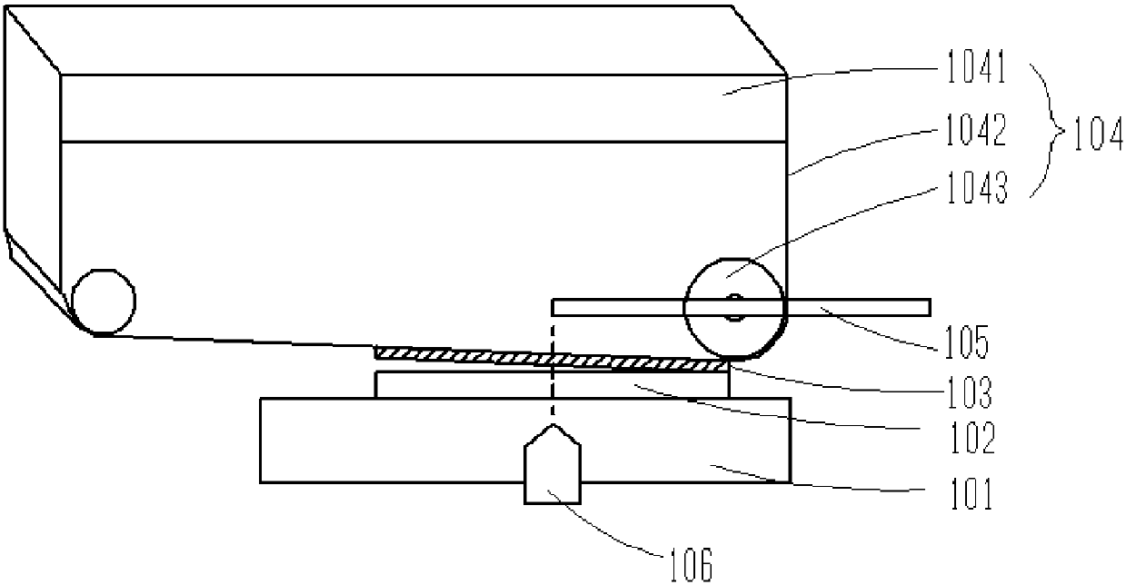
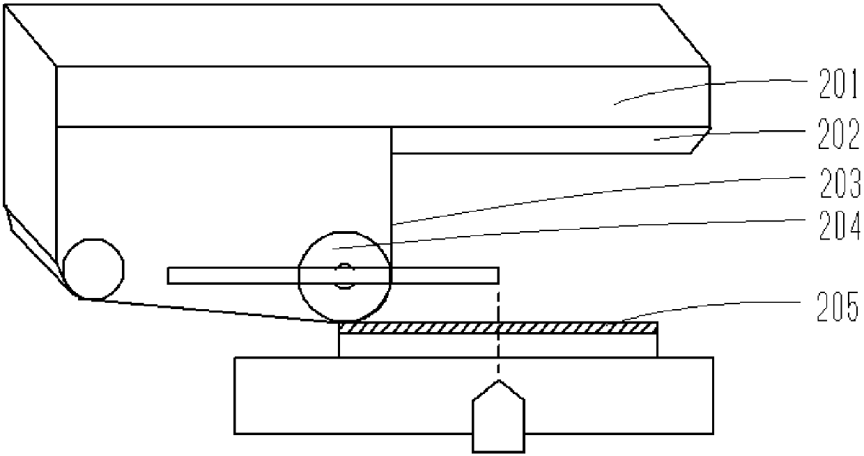
[0037] The present invention is aimed at the polarizer attaching equipment in the prior art. The method of measuring the attachment distance has low measurement accuracy, the risk of wearing the mechanism, and technical problems affecting the attaching quality and production capacity of the polarizer. This embodiment can solve this problem. defect.

[0038] Such as f...


PUM


Abstract

The invention provides polarizer attachment equipment and system. The equipment comprises an attachment platform, an attachment head, a spacing sensing component and a displacement sensor, wherein theattachment platform is used for bearing a substrate; the attachment head is arranged just above the attachment platform, comprises a roller and is used for attaching polarizer onto the substrate; thespacing sensing component is arranged at a preset position of the attachment head and is used for moving relative to the substrate according to the attachment action of the roller; the displacement sensor is arranged on the attachment platform relative to the spacing sensing component and is used for sensing a displacement of the attachment head in a vertical direction and the position and the displacement of the spacing sensing component; and the spacing sensing component is positioned in a preset sensing range of the displacement sensor. The displacement sensor is used for sensing the attachment spacing by virtue of variation of the displacement of the spacing sensing component, so that the problems that the accuracy of the measured polarizer attachment spacing is low and the attachmentquality and capacity are low are solved.

Description

technical field [0001] The invention relates to production equipment in the manufacturing process of liquid crystal displays, in particular to a polarizer attaching equipment and system. Background technique [0002] At present, in the attachment process of small and medium-sized polarizers, most of them use an adhesive sheet and an attachment roller (roller) to attach the polarizer on the surface of the substrate. This process has high attachment speed and good attachment quality. However, the optimization of the attachment parameters of this process is generally obtained through experience, such as attachment speed, attachment pressure, attachment gap (spacing), and the different types of polarizers, the parameters of the attachment process have not been well obtained. control. As one of the important parameters, the attachment gap has a great influence on the attachment quality. [0003] At present, the traditional method of measuring and attaching the gap is to use a ...

Claims


Application Information

Patent Timeline
Patent Type & Authority Applications(China)
IPC IPC(8): G02F1/13
CPCG02F1/1303
Inventor 蔡灿亮蔡志勇
Owner WUHAN CHINA STAR OPTOELECTRONICS TECH CO LTD
Why Eureka
Try Eureka