Liquid-crystal display device

A liquid crystal display device and display panel technology, applied in nonlinear optics, instruments, optics, etc., can solve the problems of low ambient light transmission, low polarizer transmittance, reduced resolution and brightness, etc., and reduce production. cost effect

Active Publication Date: 2018-03-20
BOE TECH GRP CO LTD
View PDF7 Cites 51 Cited by
  • Summary
  • Abstract
  • Description
  • Claims
  • Application Information

AI Technical Summary

Problems solved by technology

[0003] Because the existing liquid crystal display device needs to use two layers of polarizers, not only the cost of the liquid crystal display device is higher, but also because the transmittance of the polarizers is low, so the liquid crystal display device makes the external environment light less when it realizes transparent display. through the lower
In order to improve the overall transmittance of the liquid crystal display device, the prior art generally adopts the method of pixel division in pixel design, such as figure 2 As shown, a pixel is divided into a display area 03 and a transparent area 04, and only the display area 03 has changes in brightness and color. Although this method can greatly increase the transmittance, it will result in a significant decrease in resolution and brightness.

Method used


Image

  • Liquid-crystal display device
  • Liquid-crystal display device
  • Liquid-crystal display device

Examples


Embodiment Construction

[0036] The following will clearly and completely describe the technical solutions in the embodiments of the present invention with reference to the accompanying drawings in the embodiments of the present invention. Obviously, the described embodiments are only some, not all, embodiments of the present invention. Based on the embodiments of the present invention, all other embodiments obtained by persons of ordinary skill in the art without making creative efforts belong to the protection scope of the present invention.

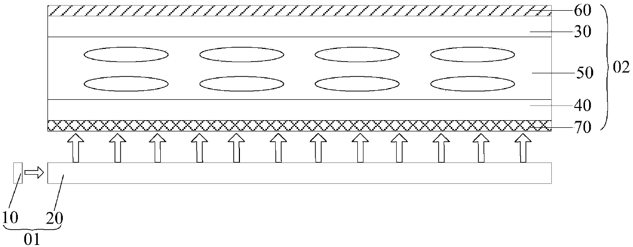
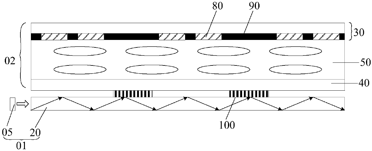
[0037] An embodiment of the present invention provides a liquid crystal display device, as shown in FIG. 3( a ) and FIG. 3( b ), including a display panel 02 and a backlight module 01 .

[0038] The backlight module 01 includes a light-emitting component 05 and a light guide plate 20; after the light emitted by the light-emitting component 05 enters the light guide plate 20 at a certain angle range, total reflection occurs in the light guide plate 20; the displ...


PUM

PropertyMeasurementUnit
thicknessaaaaaaaaaa
thicknessaaaaaaaaaa

Abstract

The embodiment of the invention provides a liquid-crystal display device, and relates to the technical field of liquid-crystal display. By the adoption of the liquid-crystal display device, the resolution and illumination of display are not reduced when transparent display is achieved. A backlight module includes a luminescence part and a light guide plate; after entering the light guide plate ina certain angle range, light transmitted by the luminescence part is totally reflected; a display panel includes a first substrate, a second substrate and a liquid crystal layer; the second substrateis close to the backlight module; the first substrate includes colorful light resistance patterns and light shading patterns, wherein the light shading patterns are used for partitioning the colorfullight resistance patterns and enabling polarized light in a first polarization direction to transmit; the liquid-crystal display device further includes first gratings which are arranged at the side,close to or away from the display panel, of the light guide plate, and the orthographic projections of the first gratings on the light shading patterns are located within the borders of the light shading patterns; the first gratings are used for enabling light which is totally reflected in the light guide plate to be emergent as collimated polarized light, the polarization direction of the collimated polarized light serves as a second polarization direction, and the first polarization direction is perpendicular to the second polarization direction.

Description

technical field [0001] The invention relates to the technical field of liquid crystal display, in particular to a liquid crystal display device. Background technique [0002] The structure of the current liquid crystal display device is as follows: figure 1 As shown, it includes a backlight module 01 and a display panel 02. The backlight module 01 includes a light source 10 and a light guide plate 20. The display panel 02 includes a first substrate 30, a second substrate 40, and a substrate arranged on the first substrate 30 and the second substrate 40. The liquid crystal layer 50 between them also includes a first polarizer 60 disposed on the side of the first substrate 30 away from the liquid crystal layer 50 and a second polarizer 70 disposed on the side of the second substrate 40 away from the liquid crystal layer 50 . [0003] Because the existing liquid crystal display device needs to use two layers of polarizers, not only the cost of the liquid crystal display device...

Claims


Application Information

Patent Timeline
Patent Type & Authority Applications(China)
IPC IPC(8): G02F1/13357
CPCG02F1/133615G02F1/13362
Inventor 谭纪风王维高健孟宪东陈小川赵文卿
Owner BOE TECH GRP CO LTD
Why Eureka
Try Eureka