Reactive compensation method of transformer
A transformer, capacitive reactive power technology, applied in reactive power compensation, reactive power adjustment/elimination/compensation, AC network circuit, etc., can solve problems such as poor transformer compensation effect, improve power factor, overcome technical bias , the effect of reducing the power factor is too low
- Summary
- Abstract
- Description
- Claims
- Application Information
AI Technical Summary
Problems solved by technology
Method used
Image
Examples
Embodiment 1
[0025] A method for reactive power compensation of a transformer according to the present invention comprises the following steps:
[0026] a. Collect basic transformer data, active power P2 and reactive power Q2 on the secondary side of the transformer;
[0027] b. Use the active power P2 and reactive power Q2 to calculate the secondary side power factor £2;
[0028] c. Calculate the theoretical power factor £1 of the secondary side of the transformer by using the basic data of the transformer;
[0029] d. When the power factor difference £3 is greater than or equal to 0.1, calculate the maximum capacitive reactive power Q required by the transformer C , where £3=£2-£1;
[0030] e. Use the maximum capacitive reactive power Q C Calculate the number of columns connected to the compensation capacitor array that needs to be connected, and then connect it to the secondary current loop on the primary side of the transformer.
[0031] When the power factor difference £3 is less ...
Embodiment 2
[0041] After the existing transformer test data, the power factor of the secondary side is £2=0.89, and the theoretical power factor of the secondary side of the transformer is calculated£1=0.74, Q c =484.5KVA. Q c Rounding off to compensate 500KVA, use 20 25KVA capacitor banks to form a whole column. Therefore, it is necessary to connect the 20-way capacitor bank to the main line of the secondary circuit of the primary side of the transformer through a contact switch.
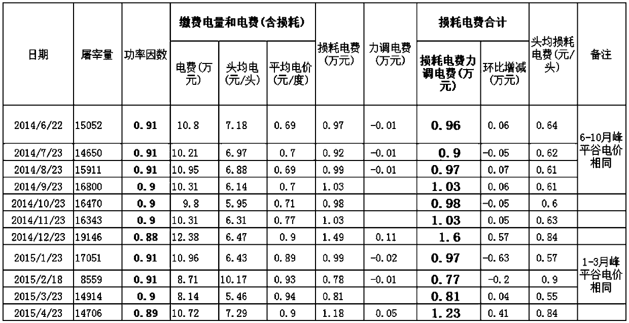
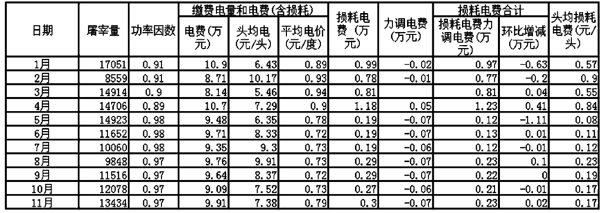
[0042] Such as figure 1 , figure 2 and image 3 Shown: vs. figure 1 and figure 2 ,
[0043] figure 1 For the data after selecting the low-voltage side for reactive power compensation, the same Q c The obtained power factor is 0.89; since the difference between £2 and £1 is greater than 0.1, the gap is very large, so use the same Q c The main line of the secondary circuit on the primary side of the transformer is compensated to obtain figure 2 According to the data, the actual power factor is incr...
PUM
 Abstract
Description
Claims
Application Information
 - R&D
- Intellectual Property
- Life Sciences
- Materials
- Tech Scout
- Unparalleled Data Quality
- Higher Quality Content
- 60% Fewer Hallucinations
Browse by: Latest US Patents, China's latest patents, Technical Efficacy Thesaurus, Application Domain, Technology Topic, Popular Technical Reports.
© 2025 PatSnap. All rights reserved.Legal|Privacy policy|Modern Slavery Act Transparency Statement|Sitemap|About US| Contact US: help@patsnap.com


