Communication equipment with mainboard protection function

A protection function and communication equipment technology, which is applied in the construction parts of electrical equipment, cooling/ventilation/heating transformation, electrical components, etc., can solve the problems of poor heat dissipation, residual heat, and damage to the main board of communication equipment, so as to prevent residual heat , Good cooling effect, simple structure

Inactive Publication Date: 2018-03-20
新昌县年丰机械厂
View PDF0 Cites 5 Cited by
  • Summary
  • Abstract
  • Description
  • Claims
  • Application Information

AI Technical Summary

Problems solved by technology

[0002] In today's society, communication is an indispensable part of people's life. In today's communication equipment, the main board plays an extremely important role, and when the communication equipment is working, the main board will generate a lot of heat, and the heat must be discharged in time. Otherwise, it will have a great impact on the work performance and even cause the main board and other components to burn out, thus making the entire communication equipment unusable, and it is difficult to efficiently dissipate heat by only relying on a cooling fan in the equipment, and often residual heat will affect communication At the same time, the main board of the existing communication equipment is generally fixed on the installation board by screws, so that the heat at the bottom of the main board is difficult to get rid of, and the communication equipment will inevitably collide when it is used or transported. The screws will loosen to a certain extent, which will easily cause damage to the motherboard during the collision of the motherboard. Therefore, we propose a communication device with a motherboard protection function to solve the problem of poor heat dissipation in communication equipment and the motherboard is easily damaged.

Method used


Image

  • Communication equipment with mainboard protection function
  • Communication equipment with mainboard protection function
  • Communication equipment with mainboard protection function

Examples


Embodiment Construction

[0015] The technical solutions in the embodiments of the present invention will be clearly and completely described below in conjunction with the accompanying drawings in the embodiments of the present invention. Obviously, the described embodiments are only a part of the embodiments of the present invention, rather than all the embodiments.

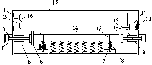
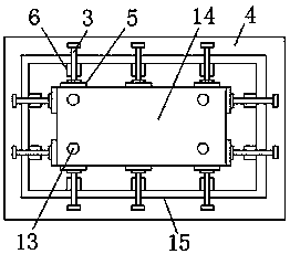
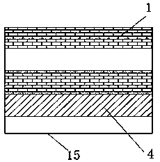
[0016] Reference Figure 1-3 , A communication device with a motherboard protection function, including a mounting shell 15, a motherboard main body 14 is arranged inside the mounting shell 15, four evenly distributed screws 13 are screwed on the main board main body 14, and the inner bottom end of the mounting shell 14 is provided There are four mounting blocks 7 evenly distributed. The bottom ends of the screws 13 are threadedly connected to the inside of the mounting block 7, and the top ends of the mounting blocks 7 are all fixed with a spring sleeve 8, and the spring sleeve 8 is equipped with a first spring. The first springs are all s...


PUM


Abstract

The invention discloses a communication device with the protection function of the main board, which comprises a mounting shell. The inside of the mounting shell is provided with a main board main body. The main board main body is screwed with four screws evenly distributed. The four mounting blocks, the bottom ends of the screws are screwed inside the mounting block, the top of the mounting block is fixed with a spring sleeve, the spring sleeve is equipped with a first spring, and the first spring is sleeved on the screw , the four side inner walls of the installation shell are fixed with positioning blocks corresponding to the main body of the main board, the positioning blocks are all threaded with horizontal threaded rods, one end of the threaded rods is connected with splints, and the side walls of the splints are all fixed There is a bearing, and one end of the threaded rod is welded on the inner ring of the bearing, and the end of the threaded rod extending to the outside of the installation shell is provided with a protective shell. The device has a simple structure, is easy to install and disassemble, and has the functions of dustproof, anti-collision and heat dissipation, and has strong practicability.

Description

Technical field [0001] The invention relates to the technical field of motherboards, in particular to a communication device with a motherboard protection function. Background technique [0002] In today’s society, communication is an indispensable part of people’s lives. In today’s communication equipment, the motherboard plays an extremely important role, and the communication equipment will generate a lot of heat on the motherboard when it is working, and the heat must be discharged in time. Otherwise, it will have a great impact on the work efficiency and even cause the motherboard and other parts to be burned, making the entire communication equipment unusable. It is difficult to efficiently dissipate heat by only relying on a cooling fan in the equipment, and often residual heat will affect the communication. The service life of the equipment. At the same time, the motherboard of the existing communication equipment is usually fixed on the mounting board by screws, so the h...

Claims


Application Information

Patent Timeline
IPC IPC(8): H05K7/20
CPCH05K7/20136
Inventor 徐君钢
Owner 新昌县年丰机械厂
Why Eureka
Try Eureka