Treatment bed system and control method

A treatment bed and control device technology, which is applied in the field of medical equipment, can solve the problems of the patient's lesion being in the radiation space and the patient's long time of treatment, so as to improve the treatment efficiency and reduce unnecessary radiation.

Pending Publication Date: 2018-03-23
北京新核核工程科技有限公司
View PDF15 Cites 7 Cited by
  • Summary
  • Abstract
  • Description
  • Claims
  • Application Information

AI Technical Summary

Problems solved by technology

[0005] The purpose of the present invention is to provide a treatment bed system to solve the technical problems in the prior art that the patient spends a long time receiving treatment in the treatment room, and the patient's lesion is located in the radiation space for a long time in an unexpected place

Method used


Image

  • Treatment bed system and control method
  • Treatment bed system and control method
  • Treatment bed system and control method

Examples


Embodiment 1

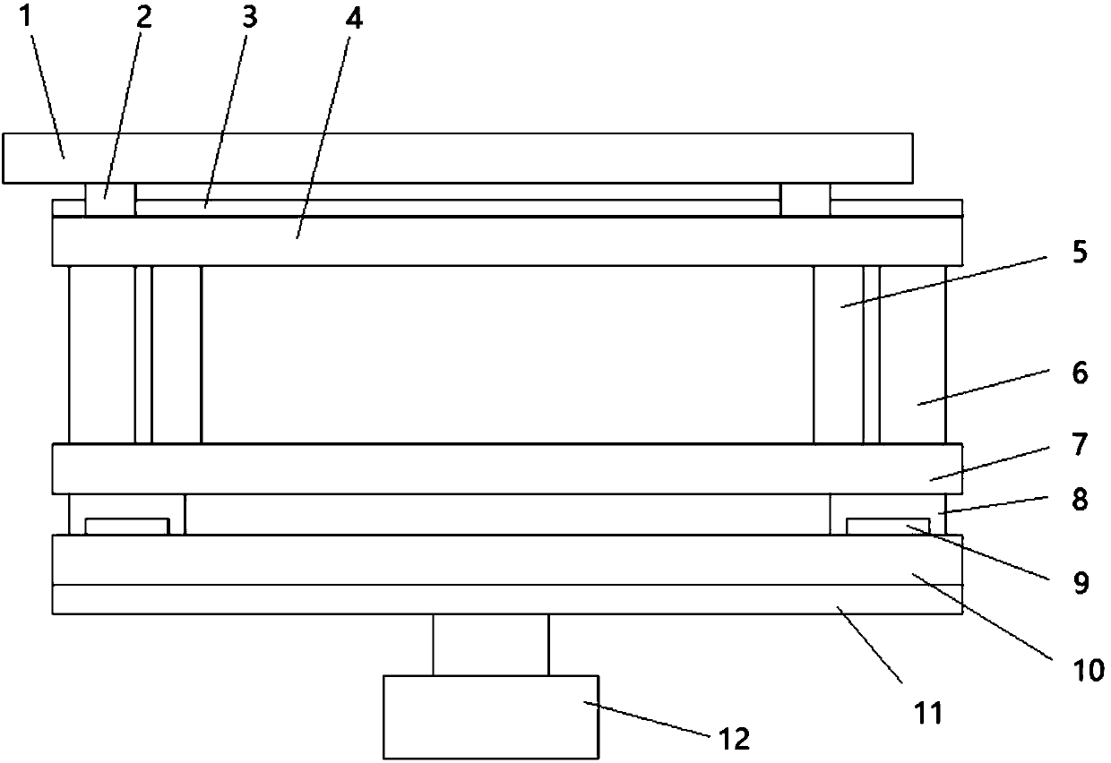
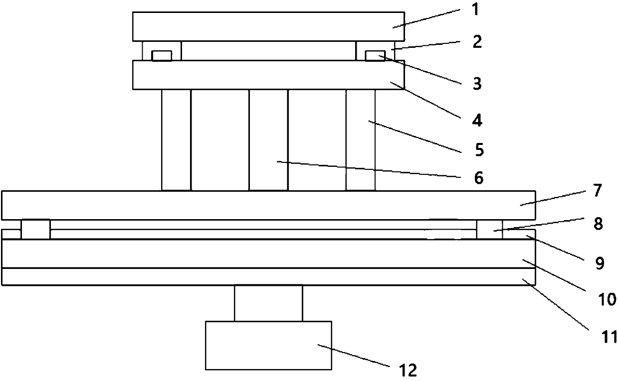
[0057] figure 1 Front view of the first treatment couch in the treatment couch system provided by the embodiment of the present invention; figure 2 It is a left view of the first treatment couch in the treatment couch system provided by the embodiment of the present invention.

[0058] In this embodiment, a treatment couch system is provided, and the treatment couch system includes a first treatment couch, a second treatment couch, a virtual irradiation source and a control device;

[0059] The first treatment couch, the second treatment couch and the virtual illumination source are all electrically connected to the control device;

[0060] The virtual irradiation source is used to emit irradiation light toward the lesion position and indicate the incident position;

[0061] The control device is used to calculate an optimal irradiation path according to the incident position and the lesion position;

[0062] The first treatment couch is used to perform six-degree-of-freed...

Embodiment 2

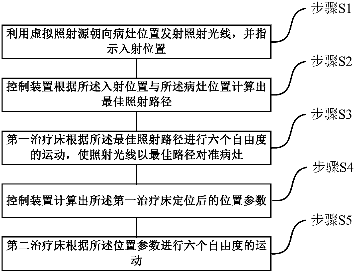
[0093] Such as image 3 As shown, this embodiment provides a treatment bed system control method, using the treatment bed system described in Embodiment 1, wherein the first treatment bed is set in the preparation room, and the second treatment bed is set in the treatment room . The treatment bed system control method includes the following steps:

[0094] Step S1, using the virtual irradiation source to emit irradiation light toward the lesion position, and indicating the incident position;

[0095] The patient lies on the first treatment bed and is positioned through the positioning groove on the bed body 1 . The virtual irradiation source emits irradiation light toward the lesion position. At this time, the path of the irradiation light entering the lesion from the incident position on the patient's body is not an optimal path.

[0096] Step S2, the control device calculates an optimal irradiation path according to the incident position and the lesion position;

[0097]...


PUM


Abstract

The invention provides a treatment bed system and a control method thereof, and relates to the technical field of medical instruments. The treatment bed system comprises a first treatment bed, a second treatment bed, a virtual irradiation source and a control device. The first treatment bed, the second treatment bed and the virtual irradiation source are electrically connected with the control device. The virtual illumination source and the first treatment bed are placed in a preparation chamber. The second treatment bed is placed in a treatment chamber. A patient is firstly in the preparationchamber, and the first treatment bed moves until the virtual irradiation source is aligned with the focus of the patient through an optimal irradiation path. The movement parameters of the second treatment bed are obtained at the moment. After that, the patient enters the treatment room. The movement parameters of the second treatment bed are determined, so that the second treatment bed moves under the control of the control device. A neutron irradiation source in the treatment room is directly aligned with the focus of the patient for treatment, and the treatment time of the patient in the treatment room is greatly shortened.

Description

technical field [0001] The invention relates to the technical field of medical devices, in particular to a treatment bed system and a control method. Background technique [0002] Existing neutron radiation therapy systems use a proton accelerator to irradiate a target to generate neutrons as a neutron source, or a nuclear reactor as a neutron source. The neutrons emitted from the neutron source are aimed at the patient's lesion for radiation therapy. [0003] The neutron channel through which neutrons are emitted is rigid, and the output direction is unique, and because neutrons have no polarity, they cannot be turned. The patient's lesions may be located in different locations, such as the chest, legs, head, etc. The treatment couch system in the prior art is generally set in the treatment room, and the patient needs to enter the treatment room and be fixed on the treatment couch system, and then adjust the treatment couch system to make the emitted neutrons reach the le...

Claims


Application Information

Patent Timeline
Patent Type & Authority Applications(China)
IPC IPC(8): A61N5/10
CPCA61N5/1001A61N5/1048A61N5/1049A61N5/1077A61N2005/1097A61N2005/109A61N2005/1019
Inventor 邱清徐刚田力
Owner 北京新核核工程科技有限公司
Why Eureka
Try Eureka