Feeding equipment of reaction container of reaction kettle

The technology of reaction vessel and feeding equipment is applied in the field of feeding equipment of reaction vessel and reaction vessel, which can solve the problems of affecting product quality, uneven reaction, excessive reaction, etc., and achieve the effect of avoiding high rotation frequency.

Pending Publication Date: 2018-03-23
CHENGDU OLYMVAX BIOPHARM
View PDF4 Cites 3 Cited by
  • Summary
  • Abstract
  • Description
  • Claims
  • Application Information

AI Technical Summary

Problems solved by technology

[0002] The reaction kettle is a container with physical or chemical reactions. The general structure of the existing reaction kettle includes a kettle body, an exhaust port, a feed port, a material outlet, a stirring device and a heating device, and the heating device is generally passed through the reactor body. A jacket is set outside the wall or heat exchange is performed through an external circulation. The main heating methods include electric heating, hot water heating, thermal oil circulation heating, far-infrared heating, external (inner) coil heating, etc.; for low boiling point reaction systems, It is not necessary to have a stirring device, which will increase the cost
In addition, the existing reaction kettles used for liquid reactions generally have a feeding port on the upper end of the kettle body and feed through a feeding pipe. This feeding method makes a large number of columnar liquid raw materials drop and react instantly When the main materials in the kettle contact, there will be phenomena such as uneven reaction and excessive reaction, which will directly affect the quality of the product, especially for viscous materials and large-volume reactors, this disadvantage is more prominent

Method used


Image

  • Feeding equipment of reaction container of reaction kettle

Examples


Embodiment 1

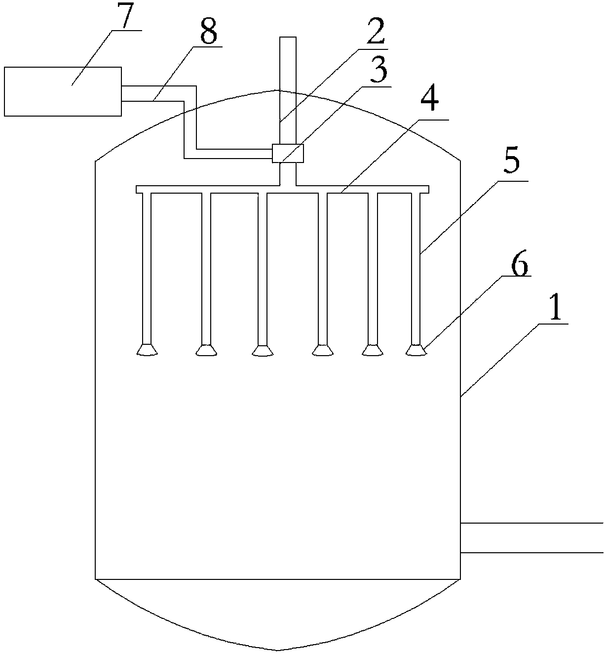
[0022] Such as figure 1 As shown, a reactor vessel feeding equipment includes a drive motor 7, a universal joint 3, an inlet pipe 2, a branch main pipe 4, a branch branch pipe 5, a reactor main body 1, and an inlet pipe 2 extends into the reactor main body 1. Inside, the inlet pipe 2 is connected with the branch main pipe 4. The branch main pipe 4 is provided with two or more branch pipes 5, and the branch branch pipe 5 communicates with the inside of the branch main pipe 4; the universal joint 3 is connected with the main shaft of the driving motor 7, and the universal joint The rotation of the joint 3 drives the rotation of the branch pipe 4.

[0023] Wherein, the drive motor 7 is connected to a frequency converter.

[0024] Wherein, the inlet pipe 2 is connected to the branch main pipe 4 through a universal joint 3.

[0025] Wherein, the lower end of the branch pipe 5 is provided with a spray head 6.

[0026] Wherein, the spray head 6 is provided with a plurality of spray holes o...

Embodiment 2

[0034] Such as figure 1 As shown, a reactor vessel feeding equipment includes a drive motor 7, a universal joint 3, an inlet pipe 2, a branch main pipe 4, a branch branch pipe 5, a reactor main body 1, and an inlet pipe 2 extends into the reactor main body 1. Inside, the inlet pipe 2 is connected with the branch main pipe 4. The branch main pipe 4 is provided with two or more branch pipes 5, and the branch branch pipe 5 communicates with the inside of the branch main pipe 4; the universal joint 3 is connected with the main shaft of the driving motor 7, and the universal joint The rotation of the joint 3 drives the rotation of the branch pipe 5.

[0035] Wherein, the inlet pipe 2 is fixed on the universal joint 3.

[0036] Wherein, the lower end of the branch pipe 5 is provided with a spray head 6.

[0037] Wherein, the spray head 6 is provided with a plurality of spray holes on the upper and lower sides.

[0038] Wherein, the main shaft of the driving motor 7 is connected to the uni...


PUM


Abstract

The invention discloses feeding equipment of a reaction container of a reaction kettle. The feeding equipment of the reaction container of the reaction kettle comprises a driving motor, a universal joint, an inlet tube, a secondary main tube, secondary branch tubes and a reaction kettle main body, wherein the inlet tube extends into the reaction kettle main body and is connected with the secondarymain tube; the two or more secondary branch tubes are arranged on the secondary main tube; the secondary branch tubes communicate with the inside of the secondary main tube; the universal joint is connected with a spindle of the driving motor; and the universal joint rotates to drive the secondary branch tubes to rotate. According to the technical scheme, by the universal joint, the secondary main tube and the secondary branch tubes, chemical raw material liquid delivered into the reaction kettle from the inlet tube is sprayed into the reaction kettle, it can be ensured that the chemical rawmaterial liquid sprayed into the reaction kettle can be uniformly sprayed, and local excessive spraying is avoided.

Description

Technical field [0001] The invention relates to the technical field of chemical processing, in particular to a reactor vessel feeding equipment. Background technique [0002] The reactor is a container with physical or chemical reaction. The general structure of the existing reactor includes a body, an exhaust port, a feed port, a discharge port, a stirring device and a heating device, and the heating device is generally installed in the body Set the jacket outside the wall or exchange heat through external circulation. The main heating methods include electric heating, hot water heating, heat transfer oil circulation heating, far-infrared heating, outer (inner) coil heating, etc.; for low boiling point reaction systems, It is not necessary to have a stirring device, which will cause an increase in cost. In addition, the existing reactors used for liquid reactions generally have a feeding port at the upper end of the kettle body and feeding through a feeding tube. This feeding m...

Claims


Application Information

Patent Timeline
Patent Type & Authority Applications(China)
IPC IPC(8): B01J19/26B01J4/00
CPCB01J4/002B01J19/26
Inventor 吴畏樊绍文颜瑜程天骏
Owner CHENGDU OLYMVAX BIOPHARM
Why Eureka
Try Eureka