Multi-angle automatic locking screw machine

A screw machine, multi-angle technology, applied in metal processing, metal processing equipment, manufacturing tools, etc., can solve problems such as low production efficiency, eye fatigue, hidden product quality problems, etc., to improve production efficiency, reduce labor intensity, and improve production. The effect of efficiency

Pending Publication Date: 2018-03-23
苏州轩明视测控科技有限公司
View PDF0 Cites 16 Cited by
  • Summary
  • Abstract
  • Description
  • Claims
  • Application Information

AI Technical Summary

Problems solved by technology

Subsequently, although there are some hand-held screw locking machines on the market, it is still necessary to manually hold the locking mechanism and use an electric screwdriver to screw the screw, which cannot meet the needs of mechanized and automated large-scale production and assembly.
Using the current manual comparison method, the production efficiency is low, only 50pcs / hour; and the labor intensity of the workers is high, requiring continuous manual adjustment; long-term operation, the workers overuse their eyes, resulting in eye fatigue, and there are hidden dangers of industrial injury to the human body; Lock payment accuracy cannot be guaranteed, and there are hidden dangers in product quality

Method used


Image

  • Multi-angle automatic locking screw machine
  • Multi-angle automatic locking screw machine
  • Multi-angle automatic locking screw machine

Examples


Embodiment Construction

[0022] The following specific examples illustrate the implementation of the present invention. Those skilled in the art can easily understand other advantages and effects of the present invention from the content disclosed in this specification.

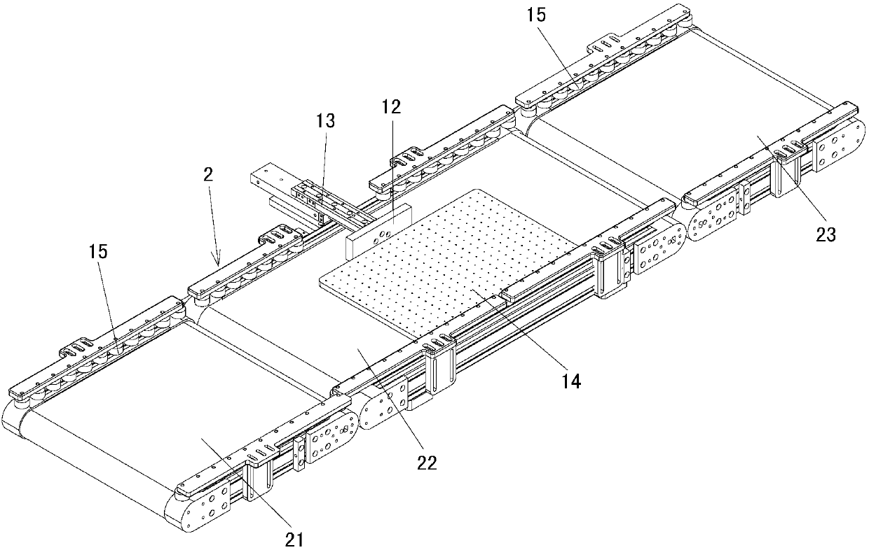
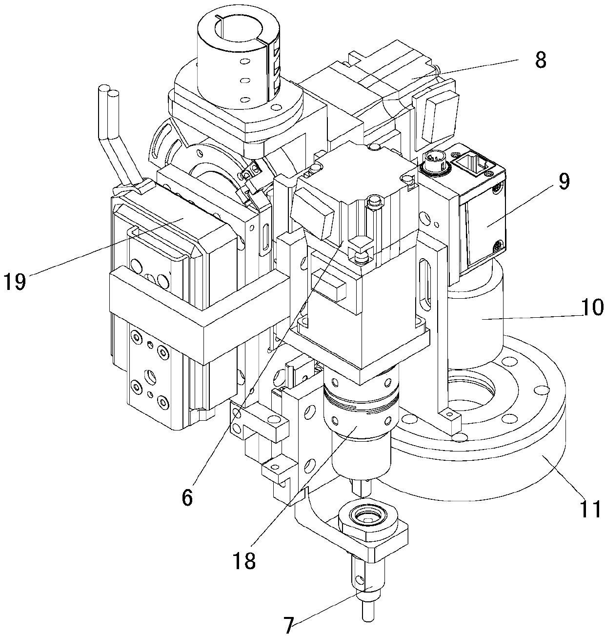
[0023] See Figure 1 to Figure 3 . It should be noted that the structure, ratio, size, etc. shown in the accompanying drawings in this specification are only used to match the content disclosed in the specification for the understanding and reading of those familiar with this technology, and are not intended to limit the implementation of the present invention Limited conditions, so it has no technical significance. Any structural modification, proportional relationship change or size adjustment should still fall under the present invention without affecting the effects and objectives that can be achieved by the present invention. The disclosed technical content must be within the scope of coverage. At the same time, the terms such as...


PUM


Abstract

A multi-angle automatic locking screw machine; including a frame, a feeding conveyor belt placed on the frame, a four-axis manipulator positioned beside the feeding conveyor belt, a screw locking mechanism installed at the working end of the four-axis manipulator, and a The screw feeder next to the feeding conveyor belt; there is also a workpiece positioning mechanism on the feeding conveyor belt; the screw locking mechanism includes a screw locking mechanism and a visual positioning mechanism; the screw locking mechanism includes a locking batch head, and a lock The vacuum suction nozzle connected to the batch bit and the angle adjustment motor that drives the rotation of the locking bit; the visual positioning mechanism includes a camera, a lens and a light source arranged in sequence from top to bottom. The invention can lock and install screws with different angles on the workpiece to be locked, which improves the work efficiency in the assembly process, reduces the labor intensity of the operators, and reduces the production cost. It has outstanding substantive features and significant progress .

Description

Technical field [0001] The invention belongs to the technical field of assembly auxiliary equipment, and relates to a multi-angle automatic locking screw machine. Background technique [0002] At present, in the manufacturing industries of electronic machinery and toy furniture, screw (screw stud) assembly operations are widely used. At this stage, the fields of mobile phones, computers, and electronic circuits all involve screw fastening. For precision products, the complexity of the shape and the appearance requirements of the screws, in terms of manual processing conditions, the quality inspection is often not up to standard, which makes the output and quality of the product unstable. [0003] In the past, most screw assembly operations were performed manually. They were manually placed in the screw holes and then locked one by one with a screwdriver. There are disadvantages such as low production efficiency and high labor intensity, which are not conducive to the expansion of ...

Claims


Application Information

Patent Timeline
Patent Type & Authority Applications(China)
IPC IPC(8): B23P19/06B23P19/00
CPCB23P19/06B23P19/001
Inventor 李强张雨涛张炼彬刘金平张超
Owner 苏州轩明视测控科技有限公司
Why Eureka
Try Eureka