Tool for machining cubic shell

A shell and tooling technology, applied to metal processing equipment, metal processing machinery parts, positioning devices, etc., can solve the problems of increasing the labor intensity of the staff, increasing the workload of the staff, and not installing a dust removal mechanism, so as to reduce the cleaning work High volume, good clamping effect and wide application range

Inactive Publication Date: 2018-03-23
卢正奎
View PDF0 Cites 14 Cited by
  • Summary
  • Abstract
  • Description
  • Claims
  • Application Information

AI Technical Summary

Problems solved by technology

[0003] The height of the existing tooling for processing cube shells is fixed. When clamping the cube shell, if the height of the cube shell is relatively large, the clamping point is not at the equilibrium position of the midpoint of the cube, and the clamping effect on the cube is poor, and the existing The cube shell processing tool is not equipped with a rotating mechanism, which cannot drive the cube shell to rotate. When the staff needs to replace the processing surface, they need to manually remove the cube shell and clamp it after turning it over. The operation is troublesome and time-consuming, which increases the staff's work. Labor intensity, in addition, there is no dust removal mechanism on the existing tooling for processing the cube shell, and the processing debris generated during the process of processing the cube shell adheres to the workbench, which reduces the processing environment and is not easy to clean, which increases the work of the staff quantity

Method used


Image

  • Tool for machining cubic shell
  • Tool for machining cubic shell
  • Tool for machining cubic shell

Examples


Embodiment Construction

[0019] In order to make the technical means, creative features, goals and effects achieved by the present invention easy to understand, the present invention will be further described below in conjunction with specific embodiments.

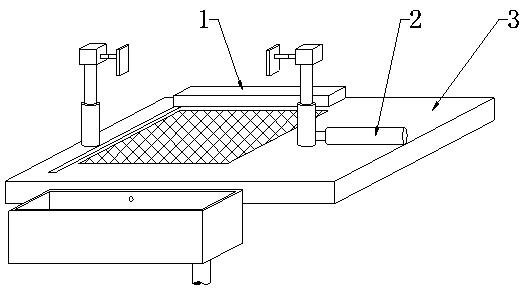
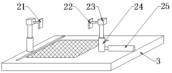
[0020] see Figure 1-Figure 3 , the present invention provides a technical solution: a tool for processing a cubic shell, including a cleaning mechanism 1, a clamping mechanism 2 and a workbench 3, the cleaning mechanism 1 is installed on the upper end of the workbench 3, and the upper end of the clamping mechanism 2 is provided with a clamping Mechanism 2, the clamping mechanism 2 is installed inside the cleaning mechanism 1.

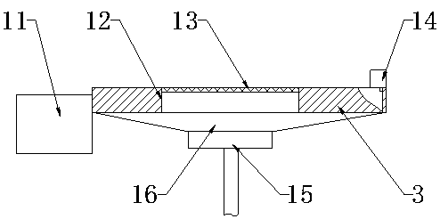
[0021] The cleaning mechanism 1 includes a dust box 11, a through groove 12, a filter screen 13, a push plate 14, a negative pressure fan 15, and a dust collection cover 16. The push plate 14 is installed on the upper end of the workbench 3, and the inside of the workbench 3 is provided with a through groove 12 , the insi...


PUM


Abstract

The invention provides a tool for processing a cubic shell, which includes a through groove, a filter screen, a push plate, a negative pressure fan, a dust collection cover, a left splint, a right splint, a motor one, an electric cylinder one and an electric cylinder two, and the push plate is installed on On the upper end of the workbench, there is a through groove inside the workbench, and a filter is installed inside the through groove. The dust collection cover is assembled on the lower end of the workbench, and the lower end of the dust collection hood is equipped with a negative pressure fan. This design can hold cubes of various heights. The use range is wide, the electric cylinder one is set on the left end of the electric cylinder two, the electric cylinder one is equipped with the motor one, the left end of the motor one is equipped with the right splint, and the left splint is set on the left side of the right splint. The processing debris is collected and cleaned. The invention is convenient to use, easy to operate, good in stability, high in reliability, and reduces labor intensity.

Description

technical field [0001] The invention is a tool for processing a cubic shell, which belongs to the technical field of cubic shell processing. Background technique [0002] At present, most of the casings of mechanical equipment are in the shape of a cube. The shape of the cubic casing is regular, and the processing difficulty is relatively low. When processing the cubic casing in the industry, there are special processing tools for the cubic casing. [0003] The height of the existing tooling for processing cube shells is fixed. When clamping the cube shell, if the height of the cube shell is relatively large, the clamping point is not at the equilibrium position of the midpoint of the cube, and the clamping effect on the cube is poor, and the existing The cube shell processing tool is not equipped with a rotating mechanism, which cannot drive the cube shell to rotate. When the staff needs to replace the processing surface, they need to manually remove the cube shell and clam...

Claims


Application Information

Patent Timeline
Patent Type & Authority Applications(China)
IPC IPC(8): B23Q3/06B23Q11/00
CPCB23Q3/062B23Q11/0046
Inventor 卢正奎
Owner 卢正奎
Why Eureka
Try Eureka