Hose pulling device

A technology of traction device and hose, which is applied in the field of hose preparation, and can solve problems affecting the subsequent processing of hoses, slipping, and affecting the accuracy of the length of the hose.

Active Publication Date: 2018-03-23
南通市通州区三槐机械制造有限公司
View PDF2 Cites 3 Cited by
  • Summary
  • Abstract
  • Description
  • Claims
  • Application Information

AI Technical Summary

Problems solved by technology

[0002] There are mainly two types of existing hose pulling devices, one is two flat belts, which flatten and clamp the hose and then pull and move. The hose is flattened under this form of traction and the hose is deformed, which affects the flexibility of the hose. The roundness of the tube further affects the subsequent processing of the hose; the other is that there is a mandrel inside the hose, and the hose is clamped and moved by a traction belt on the outside. Under this form of traction, the inner wall of the hose and the mandrel are easily connected. Sliding friction occurs. If the belt on the outer surface is clamped tighter, the friction on the inner surface will increase, and scratches will occur on the inner surface of the hose. If the belt on the outer surface is clamped loosely, slippage will occur during traction, which will affect the accuracy of the tube length.

Method used


Image

  • Hose pulling device
  • Hose pulling device

Examples


Embodiment Construction

[0026] Preferred embodiments of the present invention will be described in detail below in conjunction with the accompanying drawings.

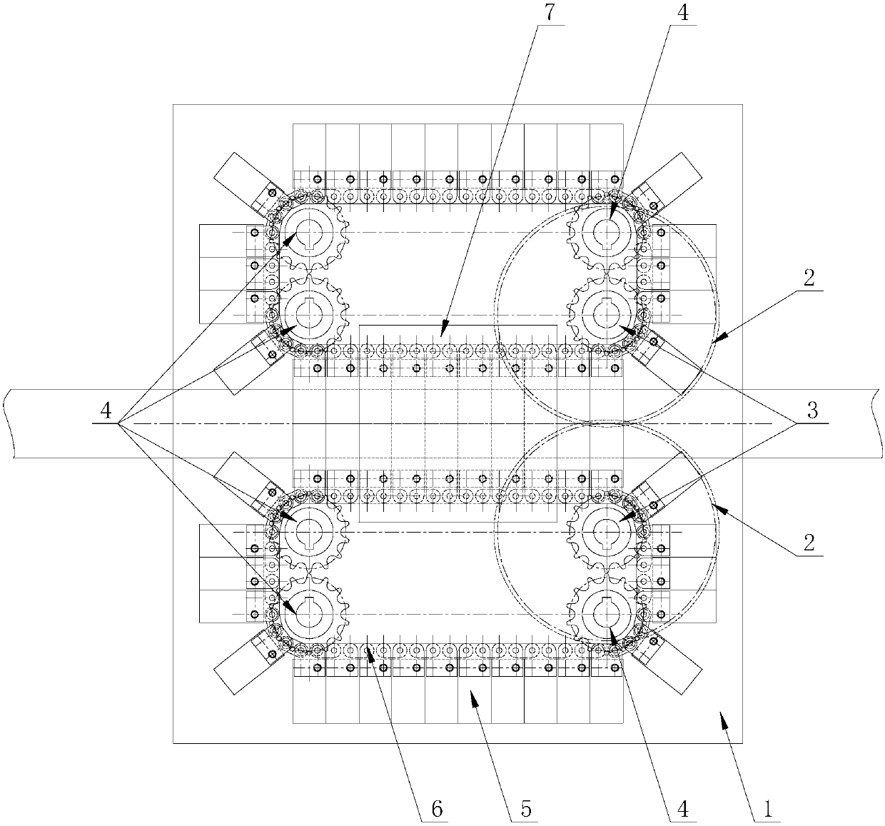
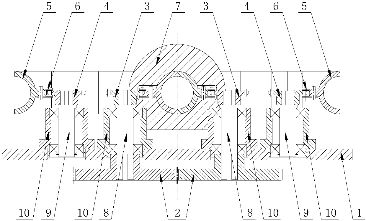
[0027] In order to achieve the purpose of the present invention, as Figure 1-2 As shown, in one of the embodiments of the present invention, a hose pulling device is provided, including the installation base plate 1, and the first pulling mechanism, the second pulling mechanism and the precision positioning sleeve 7 arranged on the installation base plate 1, the first The first traction mechanism and the second traction mechanism both include a transmission chain 6, a driving sprocket 3, a motion sprocket 4, a transmission gear 2 and 30 tube-holding half sleeves 5, and the driving sprocket 3 and the motion sprocket 4 are connected to the transmission A rotary transmission structure is formed in the inner ring of the chain 6, the transmission gear 2 is connected to the driving sprocket 3, the tube-holding half sleeve 5 is evenly arranged on t...


PUM


Abstract

The invention discloses a hose pulling device. The hose pulling device comprises a mounting base plate, a first pulling mechanism, a second pulling mechanism and a precision positioning sleeve. The first pulling mechanism and the second pulling mechanism each comprise a transmission chain, a driving sprocket, a moving sprocket, a transmission gear and multiple pipe-holding Huff sleeves. Each driving sprocket and the corresponding moving sprocket are in transmission connection with the interior of an inner ring of the corresponding transmission chain to form a rotating transmission structure. Each transmission gear is in transmission connection with the corresponding driving sprocket. The pipe-holding Huff sleeves are uniformly arranged on the corresponding transmission chains in the lengthdirection of the transmission chains. Hose channels for limiting hoses are formed between the pipe-holding Huff sleeves of the adjacent transmission chains of the first pulling mechanism and the second pulling mechanism. A positioning channel and a chain channel are arranged on the precision positioning sleeve. According to the hose pulling device, the outer surfaces of the hoses are held by thesymmetrical pipe-holding Huff sleeves and are pulled, it is guaranteed that the hoses do not deform and pulling can be conducted through whole ring holding of the outer surfaces of the hoses, the enough pulling force is provided, and it is guaranteed that the hoses do not slide in the pulling process.

Description

technical field [0001] The invention belongs to the technical field of hose preparation, and in particular relates to a hose pulling device. Background technique [0002] There are mainly two types of existing hose pulling devices, one is two flat belts, which flatten and clamp the hose and then pull and move. The hose is flattened under this form of traction and the hose is deformed, which affects the flexibility of the hose. The roundness of the tube further affects the subsequent processing of the hose; the other is that there is a mandrel inside the hose, and the hose is clamped and moved by a traction belt on the outside. Under this form of traction, the inner wall of the hose and the mandrel are easily connected. Sliding friction occurs. If the belt on the outer surface is clamped tighter, the friction on the inner surface will increase, and the inner surface of the hose will be scratched. If the belt on the outer surface is clamped loosely, slippage will occur during ...

Claims


Application Information

Patent Timeline
Patent Type & Authority Applications(China)
IPC IPC(8): B29C47/34B29L23/00B29C48/355
CPCB29L2023/005B29C48/355
Inventor 徐惠朝张艳娟顾宪彬陆观
Owner 南通市通州区三槐机械制造有限公司
Why Eureka
Try Eureka