Alignment support device for rotor of permanent-magnetic wind power generator and rotor bearing replacement method

A technology for wind turbines and supporting devices, which is used in electromechanical devices, manufacturing motor generators, casings/covers/supports, etc., can solve the problems of weakened end plate strength, poor economy, easy deformation, damage, etc. Auxiliary equipment, saving construction costs, reducing the effect of operation difficulty

Active Publication Date: 2012-07-11
DONGFANG ELECTRIC MACHINERY
View PDF5 Cites 11 Cited by
  • Summary
  • Abstract
  • Description
  • Claims
  • Application Information

AI Technical Summary

Problems solved by technology

[0005] The disadvantage of the horizontal inner rotor permanent magnet synchronous generator with the above structure is that it is difficult to disassemble during installation and maintenance. To control this magnetic attraction, when the stator, rotor, rotor bearing and other components are disassembled, it is easy to bump due to excessive magnetic attraction, and the operation is unsafe. At the same time, it is difficult to guarantee production efficiency and product quality
[0008] 1. The rotor bearing replacement process is cumbersome. During the disassembly process, the generator end cover needs to be removed first. After the replacement is completed, the generator end cover should be installed again. The entire replacement process requires a large operating space; the use of stainless steel The centering of the wedge-shaped pad needs to be fine-tuned continuously in the later stage of replacement, and the efficiency is low
[0009] 2. Since t

Method used


Image

  • Alignment support device for rotor of permanent-magnetic wind power generator and rotor bearing replacement method
  • Alignment support device for rotor of permanent-magnetic wind power generator and rotor bearing replacement method
  • Alignment support device for rotor of permanent-magnetic wind power generator and rotor bearing replacement method

Examples


Embodiment 1

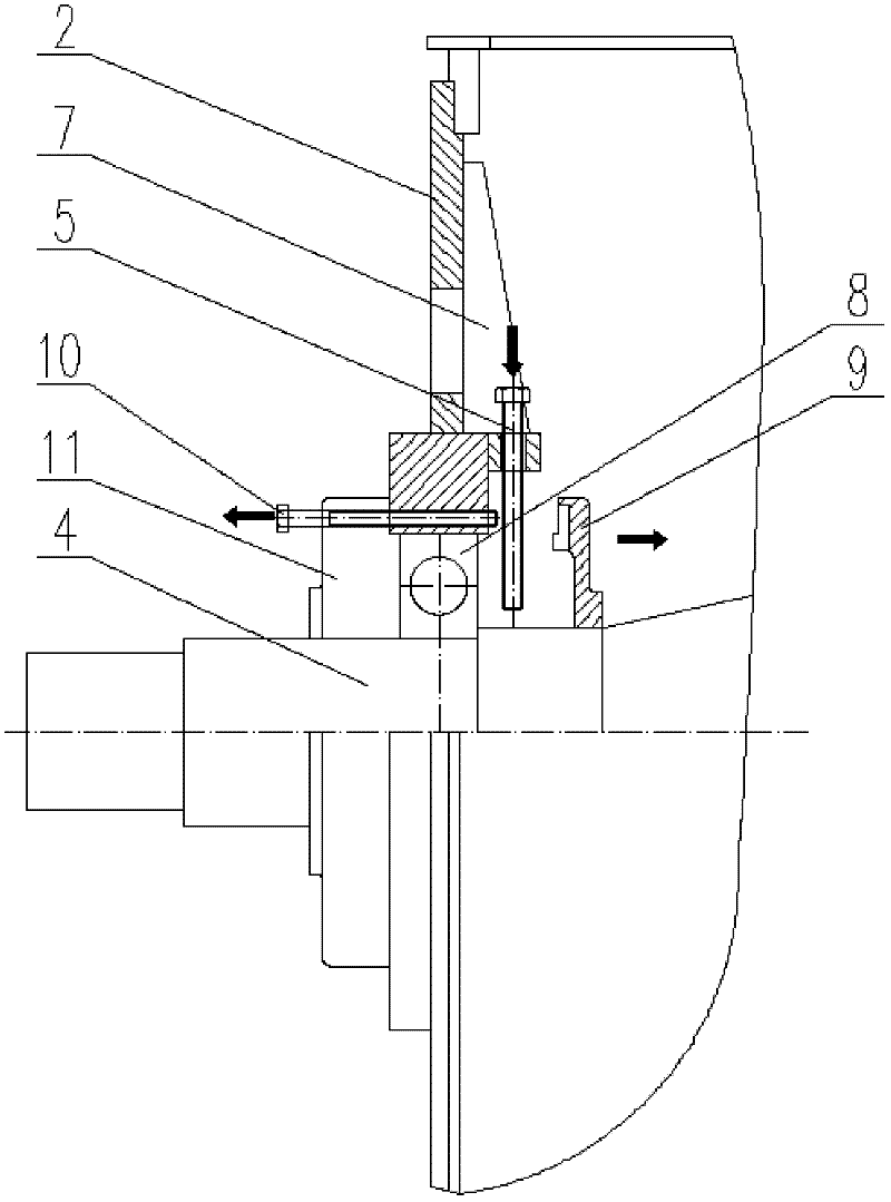
[0058] After the support bolts 5 are evenly tightened on the support plate 1, the end of the threaded section of the support bolt 5 is in contact with the outer surface of the generator shaft 4. At this time, the support bolts 5 on the three support plates 1 are used to pass through the 1 Screw-connected support bolts 5. The rotor is fixed with the generator end cover 2 as a support body, and the degree of freedom of the rotor is limited, so that the rotor is always in a state of force balance, and the rotor is prevented from being damaged due to magnetic attraction when other parts on the rotor are disassembled. The role of adsorption or impact on the stator.

[0059] When the length of the threaded section of the supporting bolt 5 is greater than the thickness of the supporting plate 1 and the sum of the distance between the supporting plate 1 and the surface of the generator shaft 4, the supporting bolt 5 is evenly tightened on the supporting plate 1, and the end of the thre...

Embodiment 2

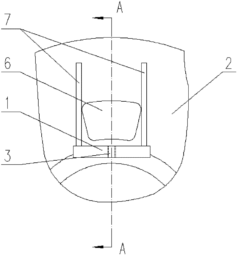
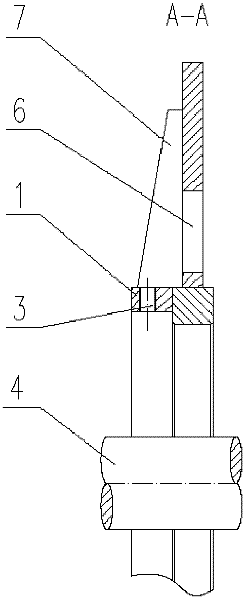
[0067] That is, taking the axis center line of the generator shaft 4 as the X axis, the center of one of the measuring air gap holes 6 is set on the XZ plane, and the other two measuring air gap holes 6 are mirror symmetrically set with respect to the XZ plane. The side of the air gap hole 6 adjacent to the generator shaft 4 is provided with a support plate 1, the number of the support plate 1 is the same as the number of the measurement air gap hole 6, the support plate 1 is arranged on the inner side of the generator end cover 2, and on the support plate 1 is provided with a threaded hole 3 and a matching supporting bolt 5, the threaded hole 3 penetrates the supporting plate 1 along the radial direction of the generator shaft 4, wherein the measuring air gap hole 6 centered on the XZ plane is close to the generator The axis of the threaded hole 3 on the support plate 1 provided on one side of the machine shaft 4 is parallel to the Z axis to balance the gravity of the rotor. ...

Embodiment 3

[0078] Example 4


PUM


Abstract

The invention discloses an alignment support device for a permanent-magnetic wind power generator. The alignment support device comprises at least three alignment support parts. Each alignment support part comprises a support plate and a support bolt, wherein the support plate is fixedly arranged on an end cover of the generator; a threaded hole is formed in the support plate, and penetrates through the support plate along the radial direction of a rotating shaft of the generator; the bolt is arranged on the threaded hole; and the bottom end of the bolt can contact the outer surface of the rotating shaft of the generator. A certain number of bolts fix the rotor by taking the end cover of the generator as a support to make the rotor always in an acting force balanced state, so that the rotor is prevented from being attracted onto or colliding with a stator under the action of gravity and magnetic attraction force in operation such as the replacement of a rotor bearing and the like; compared with the prior art in which the stator and the rotor are supported by stainless steel wedged cushion blocks, the rotor support device adopting the bolts has a simple structure, and is convenientto assemble and disassemble; and the bolts have small volumes, so that a large operating space can be provided for subsequent procedures.

Description

technical field [0001] The invention relates to a centering support device and a method for replacing parts by using the device, in particular to a centering support device for a rotor of a permanent magnet wind power generator and a method for replacing a rotor bearing by using the device. Background technique [0002] In the field of renewable energy, wind power technology is relatively mature, with lower development costs, and can greatly reduce carbon dioxide emissions. It has developed rapidly all over the world. At present, the main wind power technologies include asynchronous wind power technology, electric excitation synchronous wind power Power generation technology, permanent magnet synchronous wind power generation technology and so on. [0003] The permanent magnet wind generator is mainly composed of stator, rotor, generator end cover and rotor bearing and other components. The rotor bearing and generator end cover connect and assemble the stator and rotor of th...

Claims


Application Information

Patent Timeline
IPC IPC(8): H02K5/00H02K15/00
Inventor 李春娟齐智镝李松田段志强赵长青叶志伟
Owner DONGFANG ELECTRIC MACHINERY
Why Eureka
Try Eureka