An installation structure of a plastic trim part of a car seat

A car seat and installation structure technology, which is applied in the direction of vehicle seats, vehicle parts, special positions of vehicles, etc., can solve the problems of weak resistance to deformation, easy detachment of self-contained buckles, inconvenient assembly, etc., and achieves a wide range of applications Effect

Active Publication Date: 2020-09-08
CHONGQING CHANGAN AUTOMOBILE CO LTD
View PDF6 Cites 0 Cited by
  • Summary
  • Abstract
  • Description
  • Claims
  • Application Information

AI Technical Summary

Problems solved by technology

[0004] (1) The steel wire and the self-contained buckle cooperate with the structure, and the buckle is stuck on the steel wire in an embracing structure. Whether the self-contained buckle is installed or pulled out, the direction of force and deformation are the same, and the self-contained buckle is released. The ability to resist deformation under force is weak, the built-in buckle is easy to come off, and the installation structure is unreliable;
[0005] (2) Screws are fixed to the seat sheet metal frame. This structure requires additional sheet metal mounting bases and screw parts, and the cost is high
At the same time, the screw installation point needs to be covered. When the installation point is on the exterior side, a plastic cover needs to be added. If it is arranged in a hidden position, it is usually inconvenient to assemble and limits the space for installation tools.
[0006] CN206551909U discloses "a side shield installation structure of a car seat", which solves the problem of reducing the assembly man-hours while realizing the lightweight of the side shield
This car seat side panel mounting structure does not overcome the drawbacks of the way the car seat's large plastic trim is attached

Method used


Image

  • An installation structure of a plastic trim part of a car seat
  • An installation structure of a plastic trim part of a car seat
  • An installation structure of a plastic trim part of a car seat

Examples


Embodiment Construction

[0035] The present invention will be described in detail below in conjunction with the accompanying drawings.

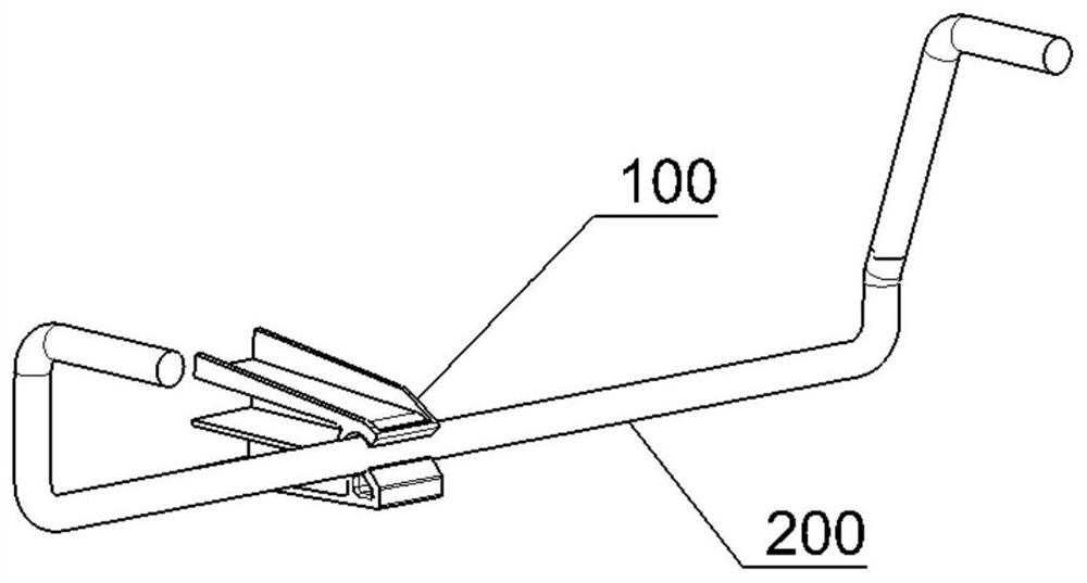
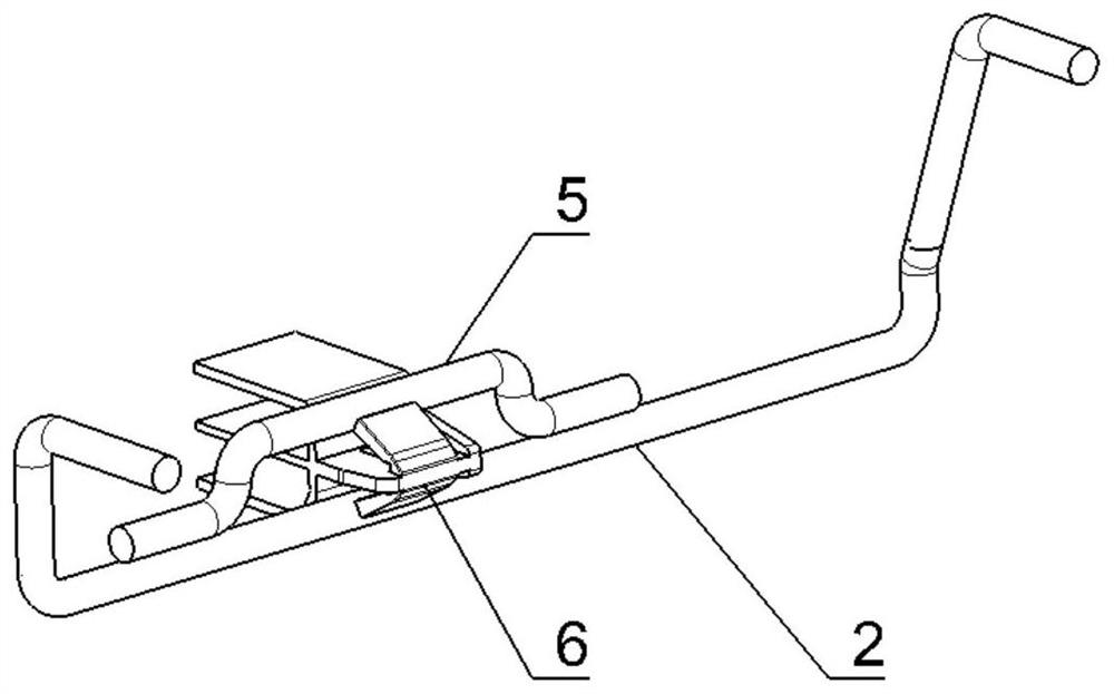
[0036] see Figure 3 to Figure 8 , a mounting structure for plastic car seat trims, comprising a plastic clip 6 integrally injection-molded with the plastic car seat trim and a steel wire buckle fixedly connected to the sheet metal frame of the seat, the plastic clip 6 and the steel wire The buckle corresponds to the fit, and its characteristics are:

[0037] The steel wire buckle is composed of a main steel wire 2 and an auxiliary steel wire 5 lapped thereon. The auxiliary steel wire 5 is U-shaped, and both ends are fixedly connected with a straight line section of the main steel wire 2, so that the auxiliary steel wire 5 There is a gap (the gap is 9mm) between the main steel wire 2 to form a steel wire buckle.

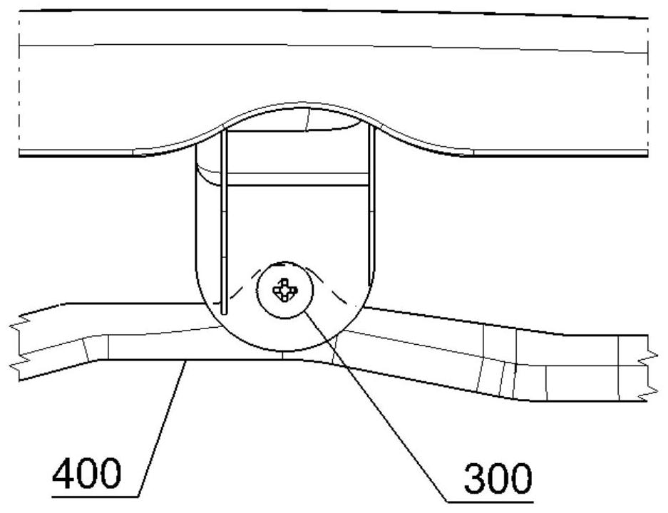
[0038] The plastic clip 6 has a clip body 12, a clip base 9 connected to the left part of the clip body, and two symmetrically arranged and arrow-shaped ...


PUM


Abstract

The invention relates to a mounting structure of a plastic decorating part of an automobile seat. The mounting structure comprises a plastic clip integrally molded with a plastic decorating part of anautomobile seat and a steel wire buckle fixedly connected to the sheet metal framework of the seat; the plastic clip and the steel wire buckle are in cooperation correspondingly; the mounting structure is characterized in that the steel wire buckle consists of a main steel wire and an auxiliary steel wire lapped onto the main steel wire; the auxiliary steel wire is U-shaped; and two ends of the auxiliary steel wire are fixedly connected with one straight segment of the main steel wire, so that a gap exists between the auxiliary steel wire and the main wire, and the steel wire buckle is formed. According to the mounting structure disclosed by the invention, the steel wire buckle and the plastic clip adopt the cooperation structure; special mounting conditions are not needed; the mounting structure is convenient to mount and is not easy to come off; and the mounting structure can be used for positioning and mounting various plastic parts such as a front seat side guard plate, a seat back plate, a back seat armrest cavity decoration plate and the like.

Description

technical field [0001] The invention relates to a car seat system, in particular to a mounting structure for a plastic trim part of a car seat. Background technique [0002] At present, people have higher and higher requirements on the appearance of car seats, and more large plastic decorative parts are used on the seats, such as front seat side guards, front guards, seat back panels, rear armrest cavity decorative panels . The commonly used fixing methods of these large plastic decorative parts include: the self-contained buckle 100 is fixed on the steel wire 200, see figure 1 ; Or be fixed on the seat sheet metal frame 400 by screws 300, see figure 2 . If these large plastic decorative parts are not fixed reliably, it may not only cause the loss of the function of the plastic decorative parts, but also become a source of abnormal noise during the driving of the vehicle, thereby affecting the comfort of the vehicle. [0003] The current fixing method of large plastic t...

Claims


Application Information

Patent Timeline
Patent Type & Authority Patents(China)
IPC IPC(8): B60N2/72
CPCB60N2/72
Inventor 王超
Owner CHONGQING CHANGAN AUTOMOBILE CO LTD
Why Eureka
Try Eureka