Ore conveyer

A technology for conveyors and ores, which is applied in the directions of conveyors, transportation and packaging, loading/unloading, etc., and can solve problems such as ore rolling and ore falling

Inactive Publication Date: 2018-03-23
四川坤元金属材料有限公司
View PDF0 Cites 1 Cited by
  • Summary
  • Abstract
  • Description
  • Claims
  • Application Information

AI Technical Summary

Problems solved by technology

[0002] Belt conveyors are usually used for ore transportation. Even if there is a small angle between the conveyor belt and the horizontal direction, the problem of ore drop is prone to occur during the upward transportation of ore. In the prior art, textures are usually set on the belt to enlarge the belt The friction between the ore and the ore is used to prevent this phenomenon, but if the ore has a large particle size, relative rolling between the ore and the ore is likely to occur, causing the ore on the upper surface to roll off

Method used


Image

  • Ore conveyer
  • Ore conveyer
  • Ore conveyer

Examples


Embodiment Construction

[0013] The present invention is further described below.

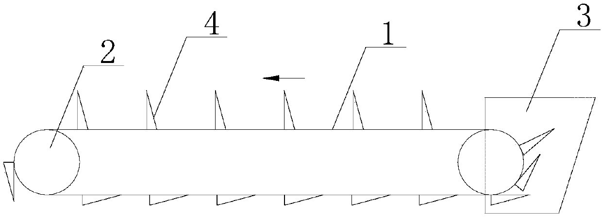
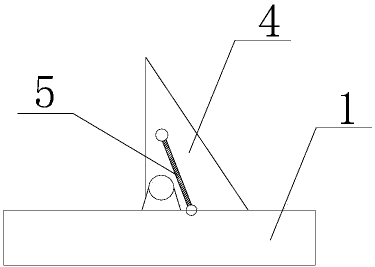
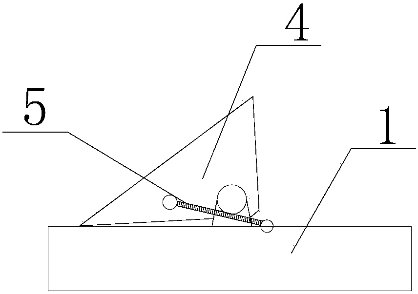
[0014] The ore conveyor disclosed in the present invention comprises a conveyor belt 1, a roller 2 and a feed hopper 3, the roller 2 is arranged at both ends of the conveyor belt 1, the feed hopper 3 is arranged at the feeding end of the conveyor belt 1, and the The conveyer belt 1 is arranged with a plurality of transverse propulsion plates 4 arranged along the conveying direction, and the vertical section of the transverse propulsion plate 4 along the axial direction of the conveyer belt 1 is a right-angled triangle structure, and the right angle position of the transverse propulsion plate 4 is in the same position as the conveyer belt. 1 is hinged, and a tension spring 5 is connected between the horizontal push plate 4 and the conveyor belt 1;

[0015] When one right-angled edge of the transverse pusher plate 4 is attached to the conveyor belt 1, the tension spring 5 is located outside the hinge point of the transve...


PUM


Abstract

The invention relates to ore conveying equipment, and discloses an ore conveying machine. The ore conveyor includes a conveyor belt, rollers and a feed hopper, the rollers are arranged at both ends of the conveyor belt, the feed hopper is arranged at the feed end of the conveyor belt, and multiple conveyor belts are arranged along the conveying direction. A horizontal pusher plate, the vertical section of the horizontal pusher plate along the conveyor belt axis is a right-angled triangle structure, the right angle position of the horizontal pusher plate is hinged with the conveyor belt, and the connection between the horizontal pusher plate and the conveyor belt There is a tension spring; when one right-angled side of the transverse push plate is fitted to the conveyor belt, the said tension spring is located outside the hinge point of the transverse push plate, and when the other right-angled side of the transverse push plate is fitted to the conveyor belt, said The tension spring is located inboard of the hinge point of the transverse propulsion plate. The ore conveyor is provided with a transverse pusher plate which not only ensures that the transverse pusher plate plays a propulsive role, but also reduces the space required for the lower part of the conveyor belt.

Description

technical field [0001] The invention relates to ore conveying equipment, in particular to an ore conveying machine. Background technique [0002] Belt conveyors are usually used for ore transportation. Even if there is a small angle between the conveyor belt and the horizontal direction, the problem of ore drop is prone to occur during the upward transportation of ore. In the prior art, textures are usually set on the belt to enlarge the belt However, if the particle size of the ore is very large, relative rolling between the ore and the ore is likely to occur, causing the ore on the upper surface to roll off. Contents of the invention [0003] The technical problem to be solved by the present invention is to provide an ore conveyor that prevents the ore from rolling down. [0004] The ore conveyor disclosed in the present invention includes a conveyor belt, rollers and a feed hopper, the rollers are arranged at both ends of the conveyor belt, the feed hopper is arranged ...

Claims


Application Information

Patent Timeline
Patent Type & Authority Applications(China)
IPC IPC(8): B65G17/14B65G65/42
CPCB65G17/14B65G65/42B65G2201/045
Inventor 桑曙光
Owner 四川坤元金属材料有限公司
Why Eureka
Try Eureka