Hidden frame glass curtain wall structure and method for mounting same

A technology of hidden frame glass curtain wall and frame, which is applied in the direction of walls, building components, building structures, etc., can solve the problems of increased construction difficulty, poor aesthetics, poor strength, and low strength, and achieves high decorativeness, structural stability, and safety. high sex effect

Inactive Publication Date: 2018-03-23
XINCHANG SICHUANG DESIGN CONSULTING CO LTD
0 Cites 35 Cited by

AI-Extracted Technical Summary

Problems solved by technology

[0002] After the existing glass curtain wall is assembled, fasteners are usually used to fix between the glass curtain walls and on both sides of the glass curtain wall. After fixing, part of the fasteners is exposed on the outside, which makes the aesthetics and strength poor, and some constructions After the completion, the glass curtain wall needs to be installed on the surface of the existing wall dur...

Method used

The glass curtain wall utilizes the outer sleeve 4 and the inner sleeve 5 to be socketed, and utilizes the lock block 57 to be embedded in the lock groove 41 to fix the panel 3, so that the adjacent panels 3 can be seamlessly connected, and finally a complete hidden frame can be realized Type installation, more decorative and more beautiful, and due to the action of the compression spring 55, it is necessary to use the magnetic block to attract the stopper 52 at the four corners of the front of the panel 3 at the same time, so that the panel 3 can be d...

Abstract

The invention provides a hidden-frame glass curtain wall structure and an installation method thereof, belonging to the field of building curtain walls. It solves the problem of poor seamless installation effect of existing glass curtain walls. The hidden frame glass curtain wall structure includes a frame, which includes columns and beams, and panels. The four corners of the back of the panels are connected to the frame through a connection mechanism. The inner sleeve on the rear pipe wall also includes a retaining ring fixed on the inner wall of the front end of the inner sleeve, a magnetic stopper located in the inner sleeve, and a compression spring located in the inner sleeve. The inner sleeve wall is provided with a lock hole , which also includes a lock block slidingly located in the lock hole, the front end of the outer cover penetrates the perforation and is placed on the inner sleeve, the inner wall of the outer cover is provided with a lock groove, and the compression spring pushes the block so that the rear end of the block is against the rear end of the inner sleeve, so that The locking surface bears against the inner end of the lock block, so that the outer end of the lock block protrudes from the lock hole and is embedded in the lock groove. The glass curtain wall can realize completely seamless hidden frame installation.

Application Domain

WallsBuilding repairs +1

Technology Topic

KeyholeRetaining ring +3

Image

  • Hidden frame glass curtain wall structure and method for mounting same
  • Hidden frame glass curtain wall structure and method for mounting same
  • Hidden frame glass curtain wall structure and method for mounting same

Examples

  • Experimental program(1)

Example Embodiment

[0039] The following are specific embodiments of the present invention in conjunction with the accompanying drawings to further describe the technical solutions of the present invention, but the present invention is not limited to these embodiments.
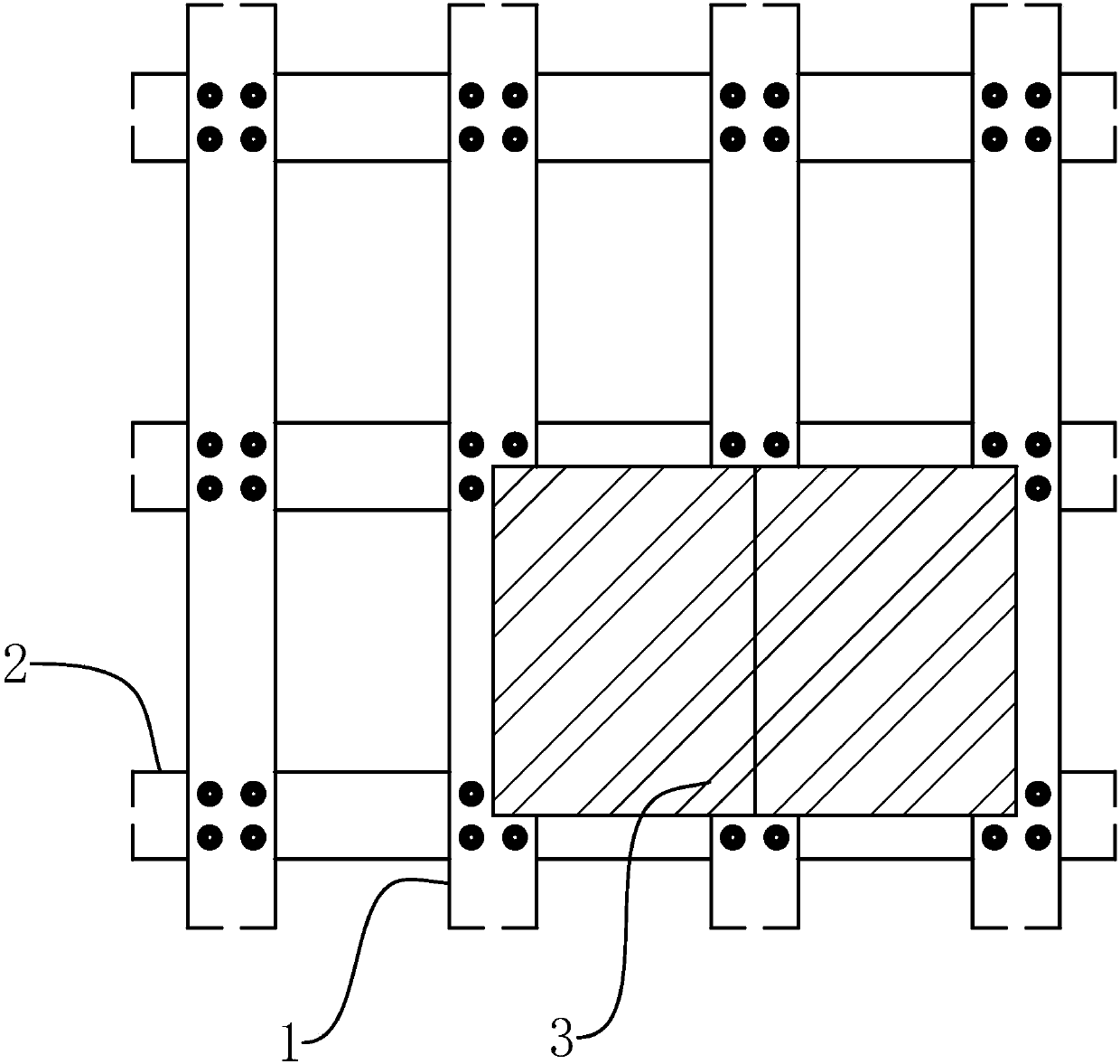
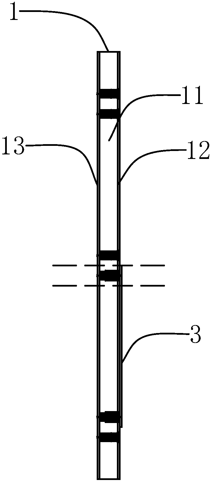
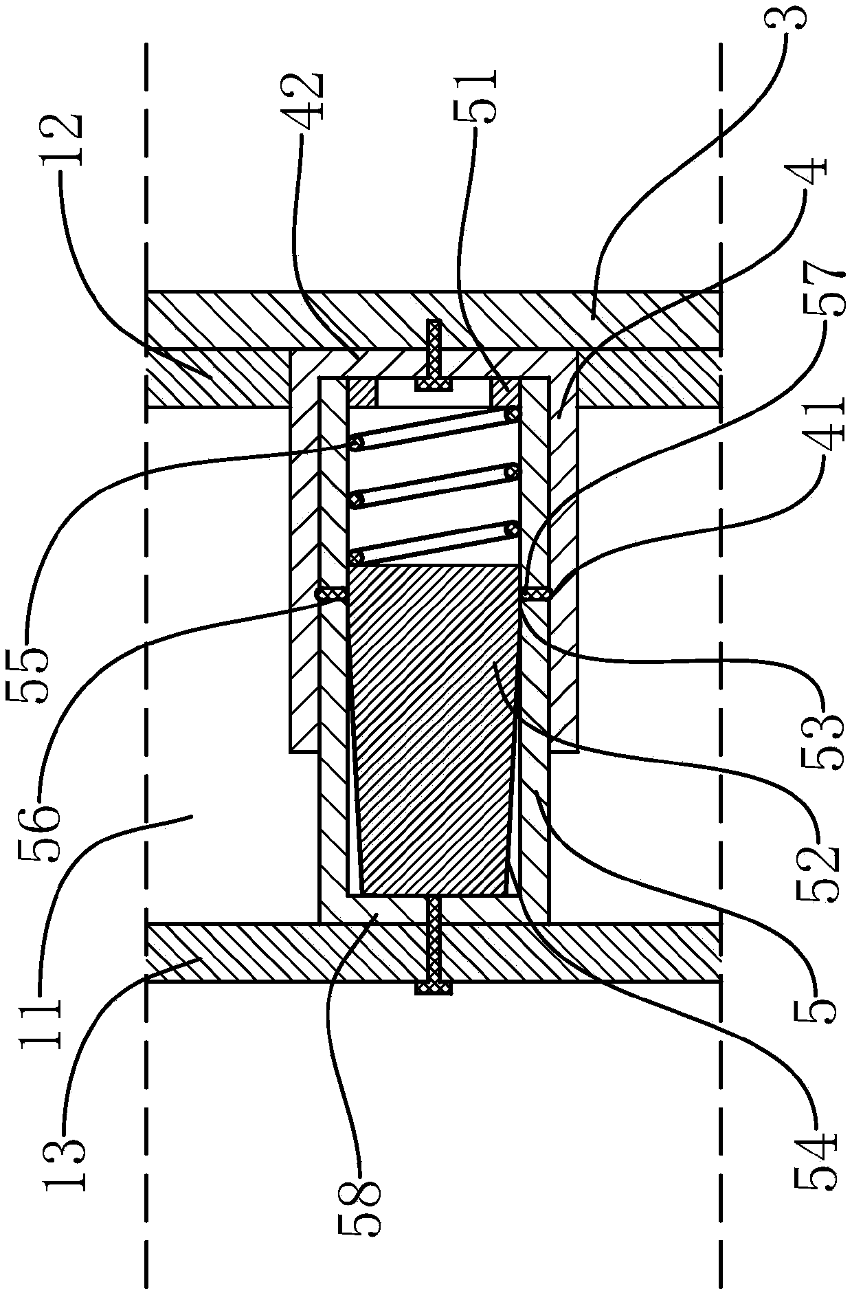
[0040] Such as Figure 1-6 As shown, a hidden frame glass curtain wall structure of the present invention includes a frame. The frame includes a plurality of vertical columns 1 parallel to each other, and a plurality of horizontal beams 2 parallel to each other are vertically connected between two adjacent vertical columns 1. The column 1 is a hollow square tube structure, and includes two parallel side tube walls 11, and a front tube wall 12 and a rear tube wall 13 parallel to each other. The end of the beam 2 is fixed perpendicularly to the side tube wall 11, and it also includes Several rectangular glass panels 3 on the frame, the back of the panel 3 near the four corners are respectively connected to the frame by a connecting mechanism. The connecting mechanism includes a round sleeve-shaped jacket 4 fixed on the back of the panel 3, and the axis of the jacket 4 is perpendicular to the back of the panel 3 and connected The mechanism also includes a circular hole-shaped perforation located on the front tube wall 12 and a circular sleeve-shaped inner sleeve 5 with a rear end fixed on the inner surface of the rear tube wall 13. The inner sleeve 5 is arranged coaxially with the perforation, and the axis is aligned with the rear tube wall 13. Vertical, it also includes a stop ring 51 fixed on the inner wall of the front end of the inner sleeve 5 and a magnetic cylindrical stop 52 movably located in the inner sleeve 5. The outer wall of the stop 52 near the front end is the locking surface 53, and the outer wall near the rear end is The unlocking surface 54 and the locking surface 53 are attached to the inner wall of the inner sleeve 5. The unlocking surface 54 gradually decreases in diameter toward the rear end of the stop 52, and also includes the inner sleeve 5, and the two ends are connected to the stop ring 51 and the stop 52 respectively. The front end of the compression spring 55 has the same outer diameter as the inner diameter of the inner sleeve 5. The wall of the inner sleeve 5 is provided with a number of circular lock holes 56. The opening direction of the lock holes 56 is arranged along the radial direction of the inner sleeve 5. The hole 56 is located at the same position in the axial direction of the inner sleeve 5. The outer wall of the lock hole 56 has a narrowing structure and also includes a cylindrical lock block 57 slidably located in the lock hole 56. Both ends of the lock block 57 are convex arc surfaces. The length of the lock block 57 is greater than the depth of the lock hole 56. The back of the panel 3 fits with the outer side of the front tube wall 12 and the front side of the beam 2, and the panel 3 is aligned with the edges of the four adjacent panels 3 up, down, left, and right. The inner diameter and outer diameter are respectively the same as the outer diameter and perforation aperture of the inner sleeve 5, and the front end of the outer sleeve 4 penetrates the perforation and is sleeved on the inner sleeve 5. The inner wall of the outer sleeve 4 is coaxially provided with an annular lock groove 41, and the groove wall of the lock groove 41 is inward. Concave arc shape, the compression spring 55 pushes the stop 52 so that the rear end of the stop 52 abuts the rear end of the inner sleeve 5, and the locking surface 53 abuts the inner end of the lock 57 so that the outer end of the lock 57 extends out of the lock hole 56, and embedded in the lock groove 41, and can attach a magnetic block to the front of the panel 3, and attract the stop block 52 to move toward the front end of the inner sleeve 5, and make the inner end of the lock block 57 abut on the unlocking surface 54 At this time, the outer end of the lock block 57 is located in the lock hole 56, and the panel 3 can be removed from the frame.
[0041] Further, the outer side of the front tube wall 12 is aligned with the front side of the beam 2, and rubber gaskets are respectively provided with the joints of the backs of two adjacent panels 3, and the backs of the four sides of the panels 3 are connected to the two adjacent uprights 1 respectively. The outer side of the front tube wall 12 is attached to the front side of two adjacent beams 2. The lock block 57 is made of magnetic adsorption material. The retaining ring 51 has external threads and is screwed on the inner wall of the front end of the inner sleeve 5. The rear end of the outer sleeve 4 and the rear end of the inner sleeve 5 are respectively fixed with an outer baffle 42 and an inner baffle 58, and the outer baffle 42 is attached to the back of the panel 3 and is fixed by a fastener located in the outer sleeve 4. 58 is attached to the inner surface of the rear tube wall 13 and fixed by fasteners. It also includes a disassembly tool 6. The disassembly tool 6 includes a handle 61 and four connecting rods 62 with one end connected to the handle 61, and the other ends of the four connecting rods 62 are respectively fixed with a suction cup 63, and the magnetic block is located in the suction cup 63, and The four suction cups 63 can be aligned with the four outer casings 4 respectively, and sucked on the front of the panel 3 near the four corners, and when the outer casing 4 is close to or sleeved on the inner casing 5, the magnetic block in the suction cup 63 faces the stopper 52 The front end of the inner sleeve 5 moves. The column 1, the beam 2, the inner sleeve 5, the outer sleeve 4 and the retaining ring 51 are all made of non-magnetic adsorption materials.
[0042] The glass curtain wall uses the outer sleeve 4 and the inner sleeve 5 to cooperate and socket, and uses the lock block 57 to be embedded in the lock groove 41 to fix the panel 3, so that the adjacent panels 3 can be seamlessly connected, and finally a completely hidden frame installation is realized. It is more decorative and more beautiful, and because of the action of the compression spring 55, it is necessary to use magnetic blocks to attract the stopper 52 at the four corners of the front of the panel 3 at the same time, and then the panel 3 can be disassembled and assembled. The safety is higher. The integrated disassembly tool 6 performs disassembly and assembly, and the locking surface 53 abuts the inner end of the lock block 57, so that the outer end of the lock block 57 is completely locked in the lock groove 41, so the structure is stable and safe after installation, and the panel 3 can be realized It is installed on the outside of the frame, and the panel 3 can be disassembled and assembled independently at the same time, so the hidden frame glass curtain wall is convenient to directly modify the existing wall.
[0043] A method for installing a hidden frame glass curtain wall structure includes the following steps:
[0044] Step 1. After the frame is installed, the outer baffle 42 is attached to the back of the panel 3 and fixed by fasteners located in the outer casing 4. The inner baffle 58 is attached to the inner surface of the rear tube wall 13 and is fastened Pieces fixed
[0045] Step 2: Insert the lock block 57 into the lock hole 56 from the inner wall of the inner sleeve 5; place the stop block 52 and the compression spring 55 in the inner sleeve 5 in sequence, and screw the stop ring 51 on the inner wall of the front end of the inner sleeve 5;
[0046] Step three, suck the four suction cups 63 on the front of the panel 3 near the four corners respectively, and align them with the four jackets 4;
[0047] Step 4. Hold the handle 61 to move the panel 3, align the four outer sleeves 4 on the back of the panel 3 and penetrate the four perforations respectively, and put them on the four inner sleeves 5 respectively. When the outer sleeve 4 is close to or sleeves on the inner sleeve When 5 is up, the magnetic block attracting block 52 in the suction cup 63 moves toward the front end of the inner sleeve 5. At this time, the block 52 attracts the lock block 57 so that the inner end of the lock block 57 abuts on the unlocking surface 54 and the lock block 57 The outer end is located in the key hole 56;
[0048] Step 5, hold the handle 61 to install the panel 3 in place, make the back of the panel 3 fit with the outer side of the front tube wall 12 and the front side of the beam 2, continue to press the middle of the panel 3 with your hand, and in turn connect the four suction cups 63 with The front of the panel 3 is separated, and the disassembly tool 6 is removed, and the compression spring 55 resets and pushes the stop 52 so that the rear end of the stop 52 abuts the rear end of the inner sleeve 5, and the locking surface 53 abuts the inner end of the lock 57 , Make the outer end of the lock block 57 extend out of the lock hole 56 and be embedded in the lock groove 41 to fix the panel 3 on the frame.
[0049] The specific embodiments described herein are merely examples to illustrate the spirit of the present invention. Those skilled in the art to which the present invention pertains can make various modifications or additions to the specific embodiments described or use similar alternatives, but they will not deviate from the spirit of the present invention or exceed the definition of the appended claims. Range.
[0050] Although this article uses more column 1, side tube wall 11, front tube wall 12, rear tube wall 13, beam 2, panel 3, outer sleeve 4, lock groove 41, outer baffle 42, inner sleeve 5, and retaining ring 51 , Stop 52, lock surface 53, unlock surface 54, compression spring 55, lock hole 56, lock block 57, inner baffle 58, disassembly tool 6, handle 61, connecting rod 62, suction cup 63, etc., but not Eliminate the possibility of using other terms. These terms are used only to describe and explain the essence of the present invention more conveniently; to interpret them as any additional limitation is contrary to the spirit of the present invention.

PUM

no PUM

Description & Claims & Application Information

We can also present the details of the Description, Claims and Application information to help users get a comprehensive understanding of the technical details of the patent, such as background art, summary of invention, brief description of drawings, description of embodiments, and other original content. On the other hand, users can also determine the specific scope of protection of the technology through the list of claims; as well as understand the changes in the life cycle of the technology with the presentation of the patent timeline. Login to view more.

Similar technology patents

Method for fabricating roof tile from stained stone metal

InactiveCN1873156ASave farmland and energyImprove decoration
Owner:高扬 +1

Powder fire-proof paint containing bromine-carbon polyester and preparation method thereof

InactiveCN101255310AImprove decorationGood weather resistance
Owner:LANZHOU UNIVERSITY OF TECHNOLOGY

Wallboard installing structure and installing method of wallboard

InactiveCN110863628AImprove decorationSimple and elegant structure
Owner:GUANGZHOU GUANGJING DECORATION MATERIAL

Classification and recommendation of technical efficacy words

  • Improve decoration
  • improve security

Powder fire-proof paint containing bromine-carbon polyester and preparation method thereof

InactiveCN101255310AImprove decorationGood weather resistance
Owner:LANZHOU UNIVERSITY OF TECHNOLOGY

Method for fabricating roof tile from stained stone metal

InactiveCN1873156ASave farmland and energyImprove decoration
Owner:高扬 +1

Wallboard installing structure and installing method of wallboard

InactiveCN110863628AImprove decorationSimple and elegant structure
Owner:GUANGZHOU GUANGJING DECORATION MATERIAL

Pesticide micro-capsule granules and preparation method thereof

InactiveCN102100229Alow toxicityimprove security
Owner:联合国南通农药剂型开发中心 +1

Method for achieving user authentication by utilizing camera

InactiveCN103678984Aimprove securityGuaranteed picture quality
Owner:湖北微模式科技发展有限公司
Why Eureka
Try Eureka