Hydraulic pump

A technology of hydraulic pump and liquid inlet, applied in the field of hydraulic pump, can solve the problems of inconvenient hydraulic pump installation, increase in size of hydraulic pump, high manufacturing cost, etc., and achieve the effect of improving efficiency, saving energy consumption and ensuring balance.

Pending Publication Date: 2018-03-23
浙江力俭新能源科技有限公司
View PDF7 Cites 0 Cited by
  • Summary
  • Abstract
  • Description
  • Claims
  • Application Information

AI Technical Summary

Problems solved by technology

[0002] Existing hydraulic pumps generally include a pump body and an eccentric shaft and a piston rod located in the pump body. The motor drives the eccentric shaft to drive the piston rod to reciprocate to achieve pressurization of the oil, but the efficiency of the existing hydraulic pump is low. When higher pressure is required, the power of the motor needs to be increased, that is, the pressure of the hydraulic pump can only be raised by using a very high-power motor, and the high-power motor is generally larger in size. In order to facilitate cooperation with the motor, the eccentric shaft will be enlarged Therefore, the size of the hydraulic pump increases, which is not only not energy-saving, but also not convenient for the installation of the hydraulic pump, and the manufacturing cost is also high.

Method used


Image

  • Hydraulic pump
  • Hydraulic pump
  • Hydraulic pump

Examples


Embodiment 1

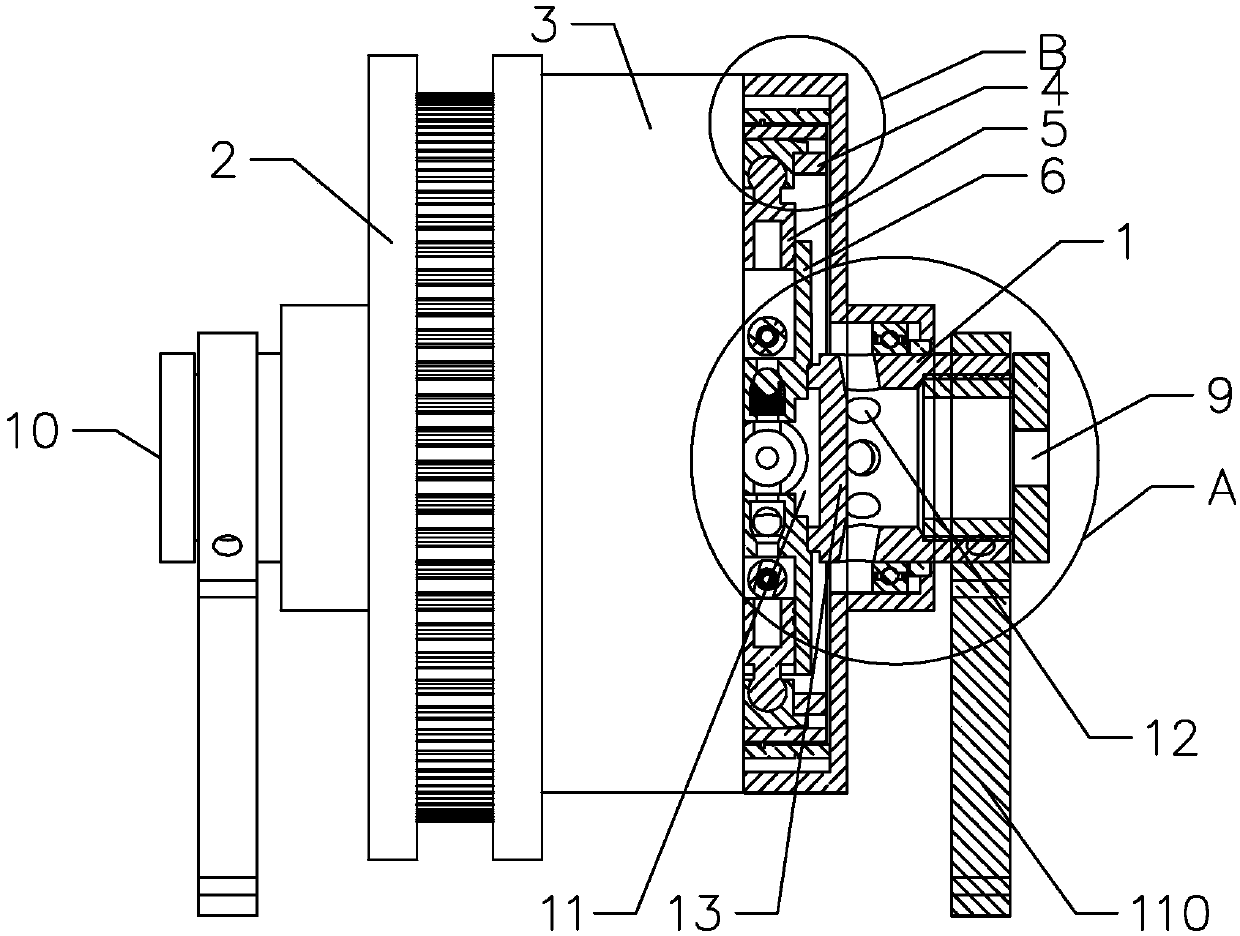
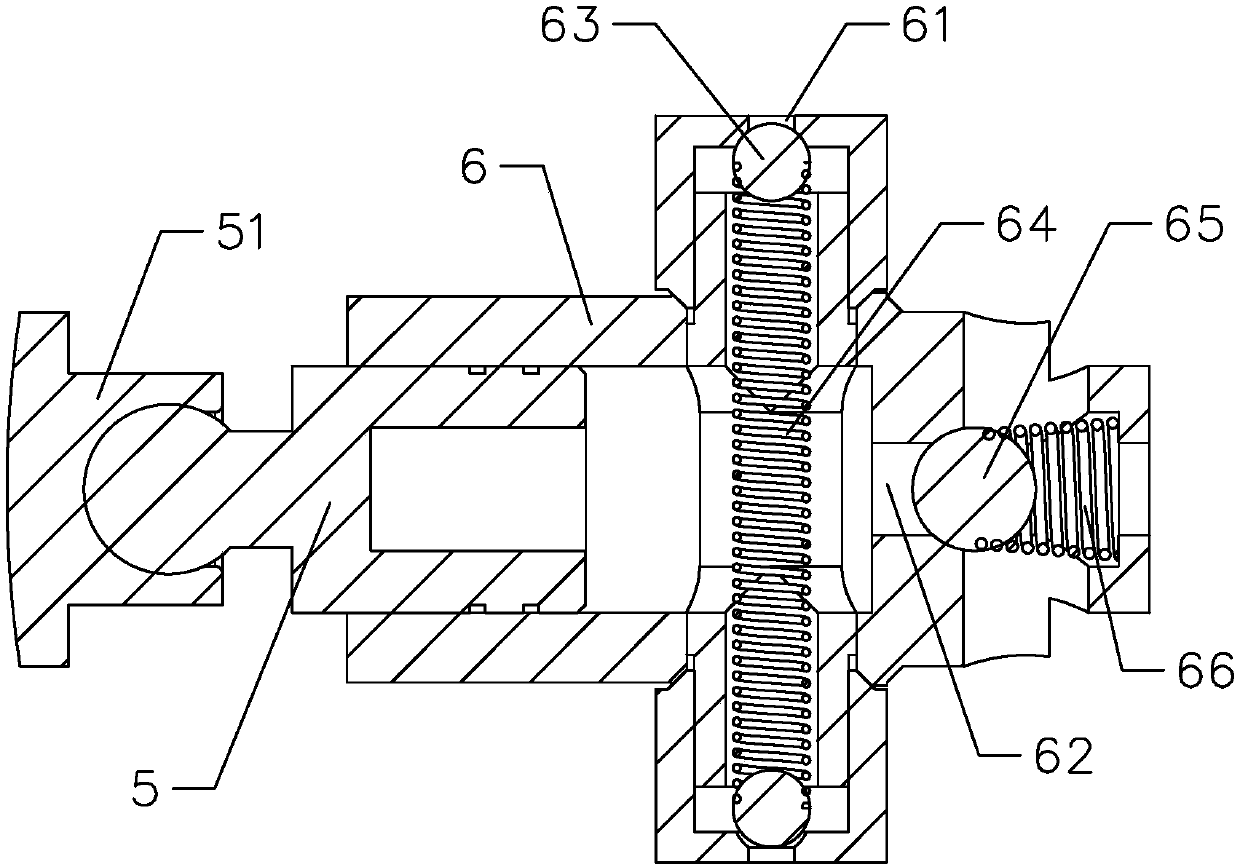
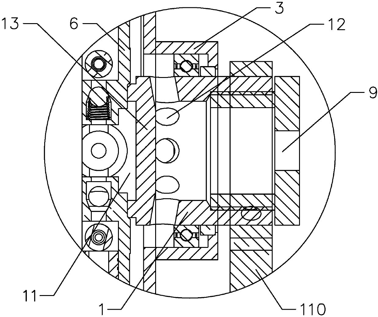
[0035] Such as Figure 1 to 4 As shown, the present invention provides a hydraulic pump including a central shaft with a hollow cavity 11, a transmission wheel 2 rotatably connected to the central shaft 1, and an eccentric sleeve 3 connected to the transmission wheel 2, and the central shaft 1 is sleeved There are ball bearings, and the transmission wheel 2 is sleeved on the ball bearings to realize the rotational connection to the central shaft 1. The central shaft 1 is a metal central shaft, specifically a stainless steel shaft, which improves the durability of the central shaft. Improve the overall durability of the hydraulic pump; the transmission wheel 2 is connected to an external power source for transmission. The eccentric sleeve 3 is provided with a steel ring 4 and a push rod assembly. The push rod assembly includes a push rod 5 arranged on the steel ring 4 and located in the center A push rod sleeve 6 on the shaft 1 and matched with the push rod 5. The push rod 5 is ...

Embodiment 2

[0044] The difference between this embodiment and the first embodiment is that the eccentric sleeve includes a first eccentric sleeve and a second eccentric sleeve.

[0045] In this embodiment, such as Figure 5 As shown, the eccentric sleeve includes a first eccentric sleeve 31 and a second eccentric sleeve 32, and the transmission wheel 2 is arranged between the first eccentric sleeve 31 and the second eccentric sleeve 32. In this way, by providing two eccentric sleeves, the external power source can be The turning torque becomes greater, which is converted into greater hydraulic pressure.

[0046] Specifically, the first eccentric sleeve 31 and the second eccentric sleeve 32 are arranged symmetrically with respect to the transmission wheel 2, so that the balance of the two eccentric sleeves during rotation can be well ensured, and the flow rate of the liquid flow can be well ensured. That is, the stability and reliability of the hydraulic pump during operation are well guarantee...

Embodiment 3

[0048] The difference between this embodiment and the first embodiment is that multiple sets of push rod assemblies distributed in a "cross" shape are arranged side by side in parallel along the axial direction of the central axis.

[0049] In this embodiment, such as Image 6 As shown, there are multiple sets of push rod assemblies distributed in a "cross" shape and are arranged side by side in parallel along the axial direction of the central axis 1, that is, multiple push rods 5 and push rod sleeves 6 are provided, and they cooperate with each other to form a liquid contact Specifically, there are three sets of push rod assemblies distributed in a cross shape. Each push rod assembly contains four push rods 5 and four corresponding push rod sleeves 6, so that when the eccentric sleeve 3 rotates , The twelve push rods 5 respectively reciprocate in the corresponding twelve push rod sleeves 6 to pressurize the liquid flow, and the pressurized liquid flows through the liquid outlet ...


PUM


Abstract

The invention provides a hydraulic pump, which comprises a center shaft with a hollow cavity, a driving wheel rotatably connected onto the center shaft, and an eccentric sleeve connected with the driving wheel. The driving wheel is in drive joint with an external power source; a steel ring and a push rod assembly are arranged in the eccentric sleeve; the push rod assembly comprises a push rod anda push rod sleeve; the push rod is arranged in an inner cavity of the push rod sleeve; a liquid inlet hole and a liquid outlet hole are formed in the push rod sleeve; the driving wheel drives the eccentric sleeve to rotate so as to drive the push rod to move in the inner cavity of the push rod sleeve in a reciprocating way; the push rod moves in the reciprocating way so as to enable a liquid flowto enter from the liquid inlet hole and be sprayed from the liquid outlet hole, so that a small rolling torque is converted into big hydraulic pressure, the efficiency of the hydraulic pump is greatlyimproved, meanwhile, the power of the external power source is reduced, and only the external power source with less power needs to be arranged; and the eccentric sleeve rotates to drive the push rodto move, so that the hydraulic pressure of the hydraulic pump can be greatly increased, the energy consumption is saved, and the effects of energy conservation and environment protection are achieved.

Description

Technical field [0001] The invention relates to a hydraulic pump. Background technique [0002] The existing hydraulic pump generally includes a pump body and an eccentric shaft and a piston rod arranged in the pump body. The motor drives the eccentric shaft to drive the piston rod to reciprocate to achieve oil pressurization, but the efficiency of the existing hydraulic pump is low. When a higher pressure is required, the power of the motor needs to be increased, that is, a motor with a large power can be used to increase the pressure of the hydraulic pump. The large-power motor is generally larger in size. In order to facilitate the cooperation with the motor, the eccentric shaft will be increased. The size of the hydraulic pump increases, which not only does not save energy, but is also inconvenient to install the hydraulic pump, and the manufacturing cost is also high. Summary of the invention [0003] The purpose of the present invention is to provide a hydraulic pump with h...

Claims


Application Information

Patent Timeline
Patent Type & Authority Applications(China)
IPC IPC(8): F04B9/02F04B53/00F04B53/10F04B53/16
CPCF04B9/02F04B53/00F04B53/1002F04B53/16
Inventor 汪力俭王溢
Owner 浙江力俭新能源科技有限公司
Why Eureka
Try Eureka