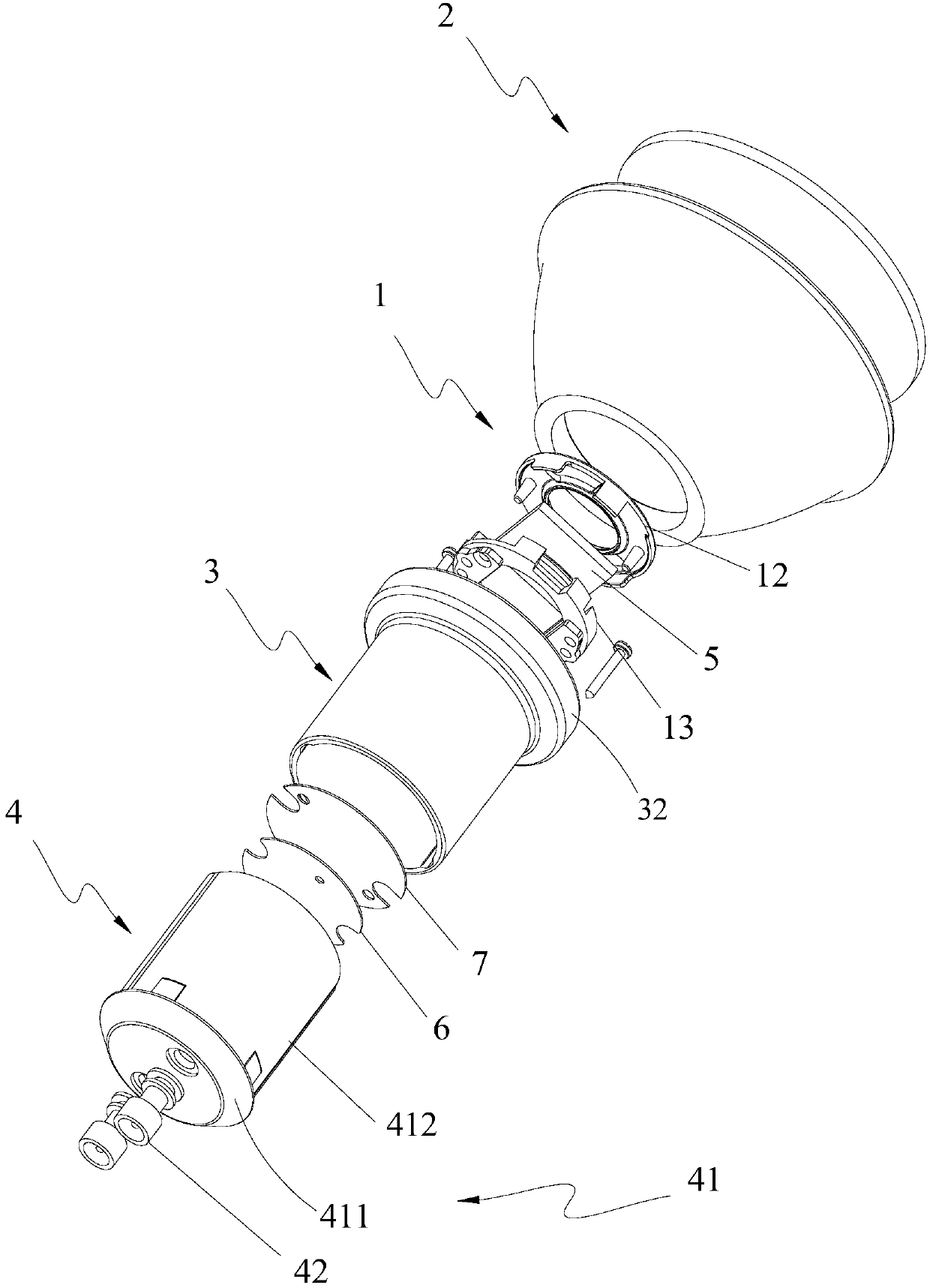
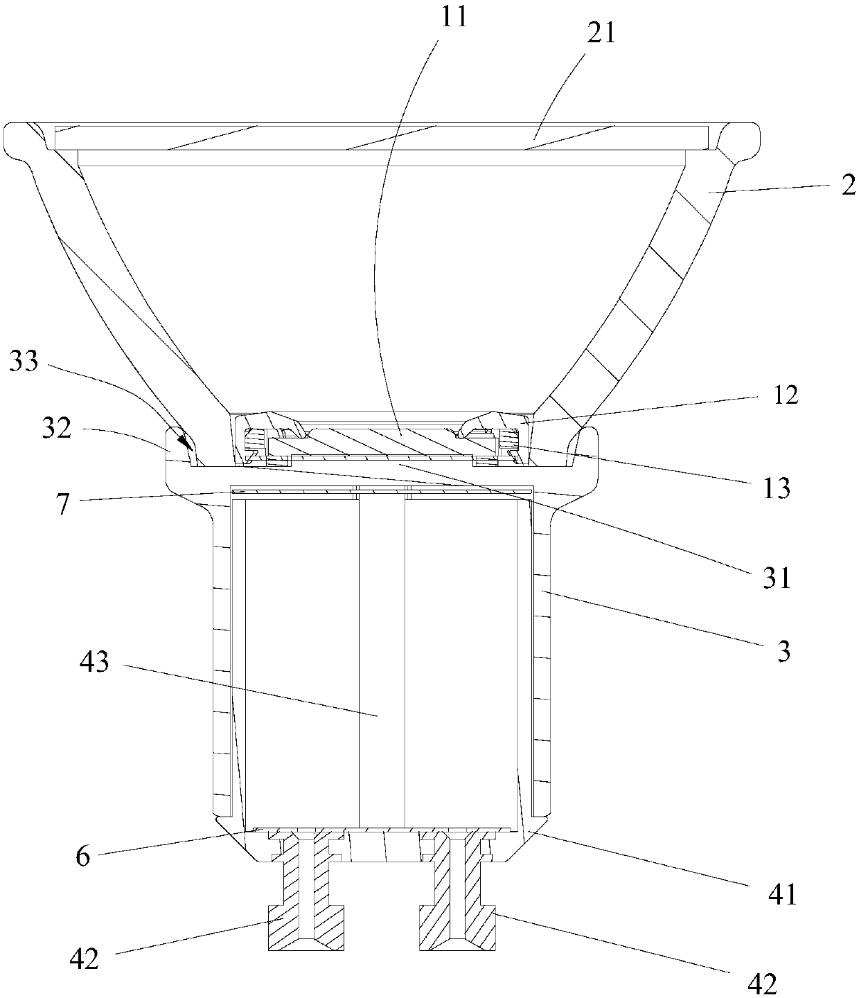
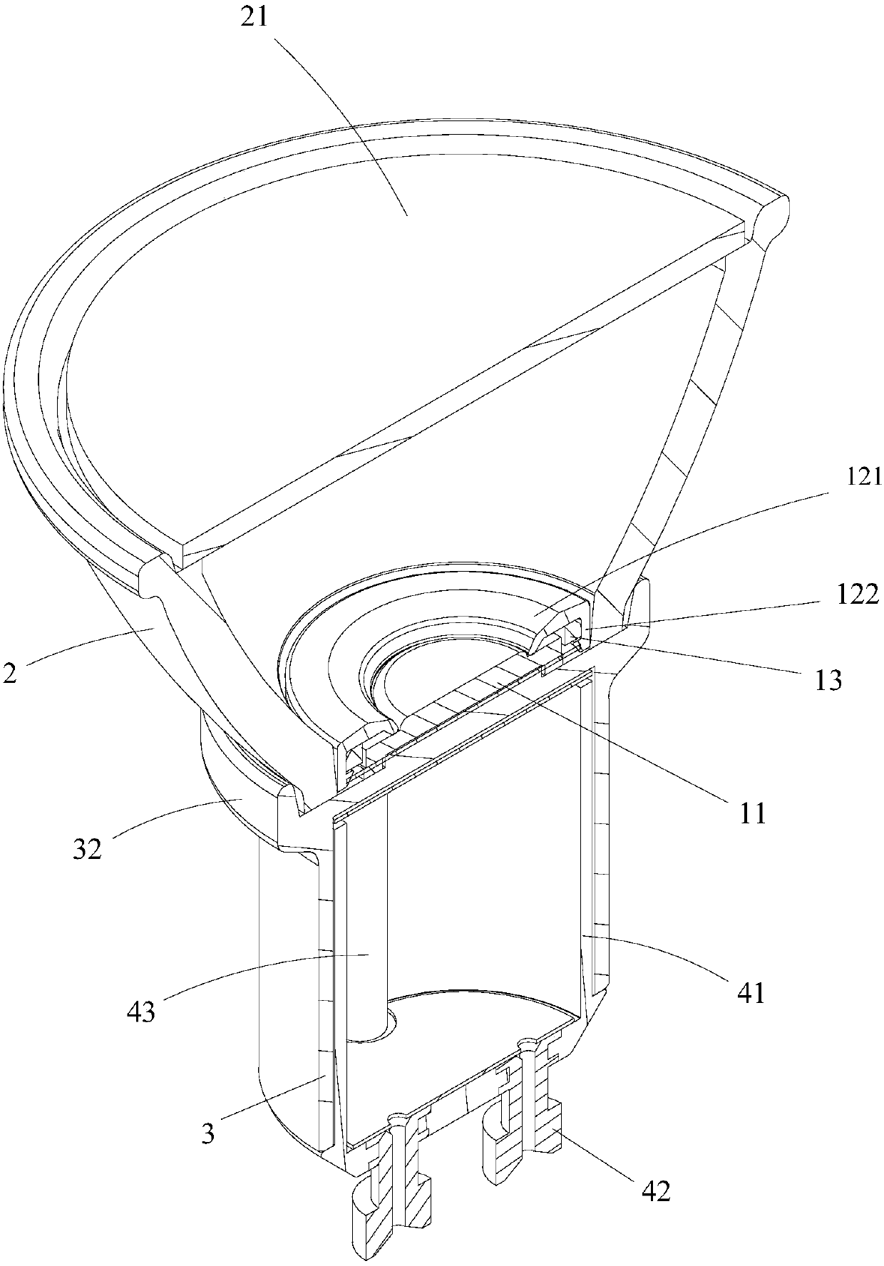
High-voltage-resistance reflector lamp

A high-voltage, lamp-cup technology, applied in lighting devices, cooling/heating devices of lighting devices, light sources, etc., can solve the problems of electrical drift, dim light, easy leakage, etc., and achieve good high-voltage resistance, simple overall structure, The effect of increasing the clearance and creepage distances

Pending Publication Date: 2018-03-23
SHENZHEN BETOP ELECTRONICS CO LTD
View PDF4 Cites 0 Cited by
  • Summary
  • Abstract
  • Description
  • Claims
  • Application Information

AI Technical Summary

Problems solved by technology

[0003] The purpose of the present invention is to provide a high-voltage resistant spotlight, which aims to solve the phenomenon of easy leakage, dim light, dead light, electrical drift and other phenomena caused by design defects of the spotlight in the prior art

Method used


Image

  • High-voltage-resistance reflector lamp
  • High-voltage-resistance reflector lamp
  • High-voltage-resistance reflector lamp

Examples


Embodiment Construction

[0018] In order to make the object, technical solution and advantages of the present invention clearer, the present invention will be further described in detail below in conjunction with the accompanying drawings and embodiments. It should be understood that the specific embodiments described here are only used to explain the present invention, not to limit the present invention.

[0019] It should be noted that when an element is referred to as being “fixed on” or “disposed on” another element, it may be directly on the other element or there may be an intervening element at the same time. When an element is referred to as being "connected to" another element, it can be directly connected to the other element or intervening elements may also be present.

[0020] It should also be noted that the orientation terms such as left, right, up, and down in this embodiment are only relative concepts or refer to the normal use state of the product, and should not be regarded as limiti...


PUM


Abstract

The invention belongs to the technical field of lamps, and provides a high-voltage-resistance reflector lamp. The high-voltage-resistance reflector lamp comprises a light source module, a glass lamp cup arranged above the light source module, a heat dissipation lamp cup arranged below the light source module and a power supply module arranged below the heat dissipation lamp cup. The top of the heat dissipation lamp cup is provided with a boss. The light source module comprises an LED light source, a light source gland arranged above the LED light source and a light source fixing base for fixing the LED light source. The power supply module is electrically connected with the LED light source, and the bottom of the LED light source is in fit with the top of the boss of the heat dissipation lamp cup. Since the light source gland is arranged above the LED light source, and the heat dissipation lamp cup with the boss is arranged below the LED light source, the height between the light source gland and the light source fixing base of the LED light source is increased, in other words, the electric clearance and creep distance between the light source gland and the light source fixing baseare effectively increased, so that the high-voltage-resistance reflector lamp has a good high-voltage-resistance effect and is simple and compact in overall structure.

Description

technical field [0001] The invention belongs to the technical field of lamps, in particular to a high-voltage-resistant spotlight. Background technique [0002] LED is a semiconductor component, and its PN junction is directly exposed, so it is easy to be exposed to static electricity. When the charges with different polarities on the two electrodes of the LED accumulate to a certain extent (generated charges or transferred charges) and cannot be released in time, once the charge energy exceeds the maximum withstand value of the LED chip, the charge will be in a very short time. Instantaneous (nanosecond level) discharge between the two electrodes of the LED generates power joules of heat, and a high temperature above 1400°C will be formed locally between the conductive layers (often at the position where the resistance value is the smallest and around the electrodes), and the high temperature will It will cause the melting between the conductive layers to produce small hol...

Claims


Application Information

Patent Timeline
Patent Type & Authority Applications(China)
IPC IPC(8): F21S8/00F21V19/00F21V29/503F21Y115/10
CPCF21S8/00F21V19/001F21V29/503F21Y2115/10
Inventor 张永辉
Owner SHENZHEN BETOP ELECTRONICS CO LTD
Why Eureka
Try Eureka