Image splicing and bending and deformation deflectionc method of long-shaft type parts based on laser ray marking

A technology of bending deformation and laser marking, which is applied in the direction of measuring devices, optical devices, instruments, etc., can solve the problems of image stitching without obvious feature points and limited measurement size, etc., and achieves easy practicality, high measurement accuracy, strong resistance The effect of interference ability

Active Publication Date: 2018-03-23
板石智能科技(武汉)有限公司
View PDF5 Cites 25 Cited by
  • Summary
  • Abstract
  • Description
  • Claims
  • Application Information

AI Technical Summary

Problems solved by technology

[0004] In view of technical fields such as performance testing of mechanical parts that require high-precision bending deformation measurement of long-axis parts, the purpose of the present invention is to provide a method for image stitching and bending deformation detection of long-axis parts marked by laser lines
The invention uses laser straight lines as splicing marks to realize the seamless splicing of cylinders with no obvious features and high-precision measurement of bending deformation of shaft parts. It is a non-contact method for measuring bending deformation of long shaft parts and solves the problem The method is difficult to realize the stitching of images without obvious feature points and the measurement size is limited.

Method used


Image

  • Image splicing and bending and deformation deflectionc method of long-shaft type parts based on laser ray marking
  • Image splicing and bending and deformation deflectionc method of long-shaft type parts based on laser ray marking
  • Image splicing and bending and deformation deflectionc method of long-shaft type parts based on laser ray marking

Examples


Embodiment Construction

[0045] The present invention will be further described below in conjunction with drawings and embodiments.

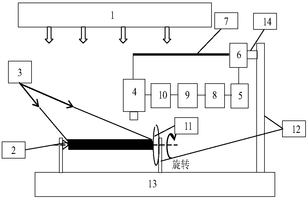
[0046] as attached figure 1 As shown, the system implemented by the present invention includes a light source system 1, a measured shaft part 2, a line laser 3, a CCD camera 4, a motor controller 5, a linear motor 6, a retractable mechanical arm 7, an image acquisition card 10, and a computer 8 , a digital image processing system 9, a chuck 11, a bracket 12, a precision vibration isolation platform 13 and a fixed mechanical arm 14.

[0047] The shaft part 2 to be tested is installed on the precision vibration isolation platform 13 through the bracket 12 horizontally with the axis, and one end of the shaft part 2 to be tested is connected to the chuck 11, and the shaft part 2 to be tested is driven to rotate by the chuck 11.

[0048] A bracket 12 is installed on the precision vibration isolation platform 13, and the linear motor 6 is installed on the top of the bracket 1...


PUM


Abstract

The invention discloses an image splicing and bending and deformation detection method of long-shaft type parts based on laser ray marking. According to the invention, a linear laser emits uniform linear laser beams which irradiate a cylindrical face of a to-be-detected shaft-type part; two images, in different axial direction positions, of the cylindrical face of the to-be-detected shaft-type part are acquired along the axis direction of the to-be-detected shaft-type part in any radial position towards the cylindrical face of the to-be-detected shaft-type part; there is an overlapping regionbetween the two images; by use of a related two-aperture splicing method based on laser marking line positions, the two images are spliced; the spliced images are subjected to coordinate conversion and is converted to be under the same coordinate system, so a splicing image is obtained; all spliced images are processed, and the slope values of the laser marking lines and axes are calculated; and finally, according to two slope values, carrying out calculation so as to obtain bending deflection errors, thereby finishing bending deflection detection. According to the invention, seamless splicingof sub-cylindrical faces without obvious characteristic points can be achieved; and the method is quite strong in anti-interference ability, low in cost and practical.

Description

technical field [0001] The invention relates to a method for measuring bending deformation of mechanical parts, in particular to an image splicing and bending deformation detection method for long-axis parts marked with laser lines. Background technique [0002] Shafts are divided into smooth shafts, stepped shafts and special-shaped shafts, etc., which have been widely used in various fields in the machinery industry. The smooth shaft is the basic type of various shaft parts, and its bending deformation measurement is the basis for characterizing the performance of mechanical shaft parts. Its bending deformation measurement is one of the important research contents of the performance test of shaft parts. The accurate measurement of bending deformation of shaft parts can ensure the improvement of the processing quality of parts. [0003] At present, the bending deformation measurement methods of shaft parts at home and abroad mainly include contact measurement methods and n...

Claims


Application Information

Patent Timeline
Patent Type & Authority Applications(China)
IPC IPC(8): G01B11/16
CPCG01B11/16
Inventor 田秋红孙政荣孙种岭
Owner 板石智能科技(武汉)有限公司
Why Eureka
Try Eureka