
Optical fiber seismic monitoring system based on back rayleigh scattering principle

A technology of Rayleigh scattering and seismic monitoring, which is applied in seismic measurement, seismology, geophysical measurement, etc., and can solve problems that are not suitable for comprehensive deployment

Inactive Publication Date: 2018-03-23
光子瑞利科技(北京)有限公司
View PDF4 Cites 4 Cited by
  • Summary
  • Abstract
  • Description
  • Claims
  • Application Information

AI Technical Summary

Problems solved by technology

But the common limitation is that they all need to place earthquake monitoring devices not far apart. Based on cost considerations, these solutions can only be used in some key protection areas, such as areas along railway lines and other areas affected by earthquakes, and are not suitable. full deployment

Method used


Image

  • Optical fiber seismic monitoring system based on back rayleigh scattering principle
  • Optical fiber seismic monitoring system based on back rayleigh scattering principle
  • Optical fiber seismic monitoring system based on back rayleigh scattering principle

Examples


Embodiment Construction

[0017] The process of Rayleigh backscattering can be described as the vector sum of backscattering of a series of random reflection units. The amplitude of the backscattering of the reflection unit obeys the Rayleigh distribution, and the phase obeys the uniform distribution. The Monte Carlo method can be used to simulate the backscattering process of reflective elements randomly distributed along the fiber path. The wavelength of the monochromatic laser is 1550nm, and the pulse width is 500ns. Under the same environmental conditions, the relationship between the simulated Rayleigh backscattering and the fiber distance is as follows Figure 5 As shown, the curve S1 represents the Rayleigh backscattering signal without vibration, the curve S2 represents the Rayleigh backscattering signal with increased vibration at 7km, and the curve S3 represents the disturbance signal (the positions of the three curves in the figure pass through the overall up and down pan to differentiate ...


PUM


Abstract

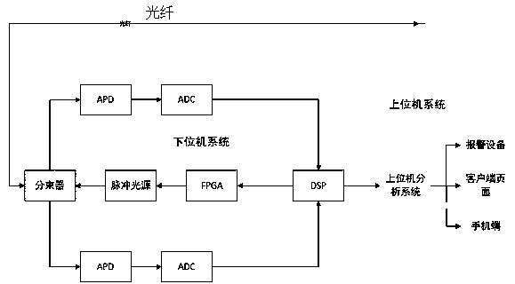
The invention provides an optical fiber seismic monitoring system based on the back rayleigh scattering principle. The system mainly comprises an optical fiber, a lower computer system which carries out data collection and analysis, an upper computer data analysis system, a client interface which is used for displaying specific seismic information, and an alarm device. According to the principle of the system, a pulse light source emits pulse light into the optical fiber, and at the same time the device detects back rayleigh scattered light at the incident end of the pulse light; and the return light intensity information is analyzed. The back rayleigh scattering regularity of the optical fiber is very strong. Under the condition that the optical fiber does not vibrate, the returned back rayleigh scattering intensity is basically fixed. When the seismic wave acts on a certain position of the optical fiber, the rayleigh scattering at the position changes. The analysis system determinesthe vibration position based on the time when the abnormal value is received. The vibration intensity is determined by analyzing the change magnitude of a vibration value. The lower computer uploads the analysis result to an upper computer. The upper computer displays alarm details and commands the alarm device to alarm.

Description

technical field [0001] The invention relates to an optical fiber seismic monitoring system, which is suitable for real-time monitoring of earthquake conditions in designated areas. The main technologies and principles used are: seismic waves cause optical fiber to vibrate, light propagates in optical fiber to produce Rayleigh scattering, etc. It belongs to the technical field of optical fiber vibration sensing, earthquake monitoring and the like. Background technique [0002] The United States is the earliest country to conduct earthquake monitoring research. The method of earthquake monitoring and early warning in the United States is to install and build multi-point earthquake alarm monitoring devices in various places. Use these devices to detect the seismic vibration waveform, and through analysis, extract the P-wave data in the seismic waveform. Since the P wave of the seismic wave is less destructive than the S wave, but the propagation speed is much faster than the ...

Claims


Application Information

Patent Timeline
Patent Type & Authority Applications(China)
IPC IPC(8): G01V1/00G01V1/18G01V1/36
CPCG01V1/18G01V1/364G01V2210/324G01V2210/121G01V1/01
Inventor 柴军杰魏嘉刘本刚李建彬张洁任晋原
Owner 光子瑞利科技(北京)有限公司
Learn More