Eureka AIR delivers breakthrough ideas for toughest innovation challenges, trusted by R&D personnel around the world.

Electronic evidence fixing method, terminal device and storage medium

A technology of electronic evidence and fixed methods, applied in the field of information security, can solve the problem of insufficient prediction of storage capacity speed and scale of storage media, insufficient prediction of forensic system scene changes, and structural design that cannot efficiently support multi-terminal, multi-task concurrent distributed Forensic analysis and other issues to achieve the effect of reducing complexity, reducing data input and output time and flash memory consumption

Active Publication Date: 2018-03-23
XIAMEN MEIYA PICO INFORMATION
View PDF7 Cites 3 Cited by
  • Summary
  • Abstract
  • Description
  • Claims
  • Application Information

AI Technical Summary

Problems solved by technology

[0014] Insufficient foresight of the speed and scale of the increase in storage capacity of the storage medium, and flaws in the structural design make the computer unable to effectively manage the memory during application
[0015] Insufficient foresight of the scene changes in the application of the forensic system, as well as flaws in the structural design, cannot efficiently support multi-terminal, multi-task concurrent distributed forensic analysis

Method used


Image

  • Electronic evidence fixing method, terminal device and storage medium
  • Electronic evidence fixing method, terminal device and storage medium

Examples


Embodiment 1

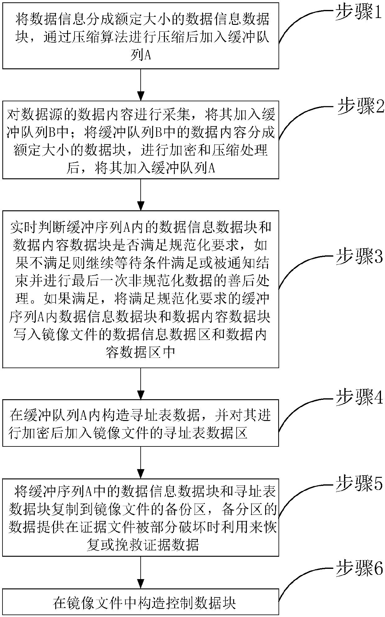
[0051] Embodiment 1 of the present invention provides a method for fixing electronic evidence, such as figure 1 , 2 As shown, it is a schematic flow chart of the electronic evidence fixing method described in Embodiment 1 of the present invention, and the method may include the following steps:

[0052] Step 1: Divide the data information into data information data blocks of a rated size, compress them through a compression algorithm, and add them to the buffer queue A.

[0053] In this embodiment, the data information is case information, including one or more of the following information: case number, evidence number, GUID (Global Unique Identifier) ​​value, inspector name, evidence fixing date and time, password Hash value, operating system platform at the time of fixation, algorithm version number, original sector number of evidence, original sector byte number, total byte number, start sector, end sector, hash value, remark information.

[0054] Since the data content n...

Embodiment 2

[0086] The present invention also provides an electronic evidence fixing terminal device, including a memory, a processor, and a computer program stored in the memory and operable on the processor, and the present invention is realized when the processor executes the computer program Embodiment The steps in the above-mentioned method embodiment, for example figure 1 The method steps of step 1-step 6 are shown.


PUM


Abstract

The invention relates to an electronic evidence fixing method, a terminal device and a storage medium. The method comprises the following steps of 1, compressing data information and adding the compressed data information to a buffer queue A; 2, collecting data contents, adding the collected data contents to a buffer queue B, encrypting and compressing the data contents in the buffer queue B, andadding the encrypted and compressed data contents to the buffer queue A; 3, judging whether data blocks in the buffer sequence A meet standardization requirements or not in real time; 4, constructingaddressing list data in the buffer queue A, encrypting the addressing list data, and adding the encrypted addressing list data to an addressing list data region; 5, copying the data blocks in the buffer sequence A to a backup region of a mirror image file; and 6, constructing a file control region in the mirror image file. Through simplified structured design, network resources comprised in computer software and hardware can be effectively and correctly fully utilized in the creation and usage processes of the evidence mirror image file.

Description

technical field [0001] The present invention relates to the technical field of information security, in particular to an electronic evidence fixing method, a terminal device and a storage medium. Background technique [0002] The first step in electronic data forensics is evidence fixation. Evidence fixation refers to the process of obtaining data from suspect computers or storage media or mobile terminals. Evidence fixation must comply with strict operational norms, and it needs to be carried out by qualified personnel using professional data acquisition tools. At the same time, the mirror file needs to be judged to be judicially valid. [0003] There are mainly two storage methods for evidence immobilization, one is to copy and store electronic evidence bit by bit on the target storage medium, and the other is to make electronic evidence into a mirror image file. The main fixed method of early electronic data forensics is the first target storage medium bit-to-bit copy s...

Claims


Application Information

Patent Timeline
IPC IPC(8): G06F3/06G06F11/14
CPCG06F3/0604G06F3/0608G06F3/0638G06F3/0659G06F11/1448G06F11/1458
Inventor 严小飞吴少华黄志炜
Owner XIAMEN MEIYA PICO INFORMATION
Why Eureka
Eureka Blog
Learn More