Mobile power distribution cabinet

A power distribution cabinet, mobile technology, applied in substation/power distribution device shell, electrical components, substation/switch layout details, etc., can solve the waste of manpower and time, handling and moving rely on manual or mechanical, weight of power distribution cabinet Large and other problems, to achieve the effect of flexible placement

Inactive Publication Date: 2018-03-23
苏州华安普新能源科技有限公司
View PDF0 Cites 2 Cited by
  • Summary
  • Abstract
  • Description
  • Claims
  • Application Information

AI Technical Summary

Benefits of technology

This new design allows for easy moving or fixing of a power distributor cabin within its own frame without having extra tools like wheelchairs attached. It also has two handles instead of one, which makes them easier to move around when needed. Additionally, there's another mechanism called a locking system where the door locks onto the machine itself while still being able to rotate freely about this axis. These technical improvements make the cabier work better because they allow for flexibility during use.

Problems solved by technology

This patented technical problem addressed in this patents relates to how to efficiently move or relocate an electricity distributor's cabinets for frequent use while still being lightweight but also allowing them to easily return back into their original position after they are taken out from production without wasting too much effort on staffing resources.

Method used


Image

  • Mobile power distribution cabinet
  • Mobile power distribution cabinet

Examples


Embodiment Construction

[0013] The present invention will be further described below in conjunction with the accompanying drawings and specific embodiments, so that those skilled in the art can better understand the present invention and implement it, but the examples given are not intended to limit the present invention.

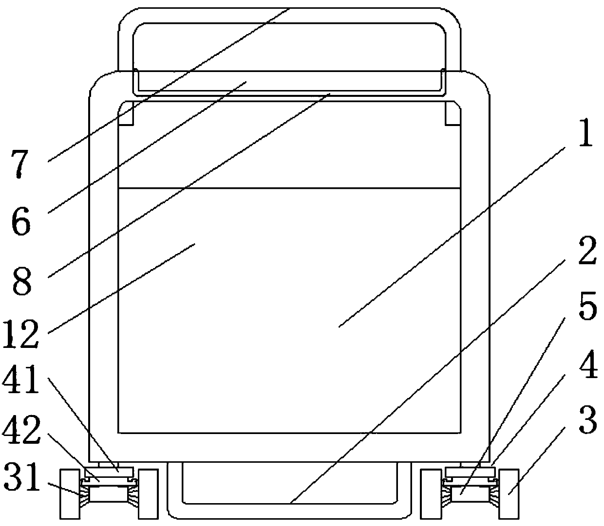
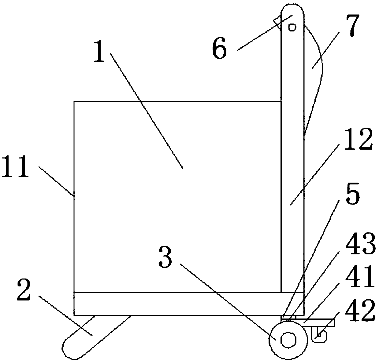
[0014] Such as figure 1 , figure 2 As shown, a mobile power distribution cabinet includes a cabinet body 1, and also includes support legs 2, two pairs of wheels 3 and a parking device 4. The support legs 2 are arranged on the side of the lower surface of the cabinet body 1 close to the cabinet door 11 to support The upper end of leg 2 is fixed on the lower surface of cabinet body 1, and the lower end of support leg 2 is inclined to the direction of cabinet door 11. The plane formed by the lower end of support leg 2 and the lowest point of wheel 3 is parallel to the lower surface of cabinet body 1. Two pairs of The wheels 3 are respectively arranged on the two corners of the low...


PUM


Abstract

The invention discloses a mobile power distribution cabinet, comprising a cabinet body, supporting legs, two pairs of wheels and a parking device. The supporting legs are arranged on the side of the lower surface of the cabinet body close to the cabinet door, and the wheels are respectively arranged on the cabinet body The lower surface is close to the two corners of the back plate, each pair of wheels is radially spaced with a number of convex ridges on the opposite surface, each pair of wheels is installed in the wheel frame through the wheel axle, the parking device includes a foot pedal and a brake pedal, a foot pedal. One end of the plate is rotatably connected with the wheel frame, a torsion spring is arranged at the connection between the foot pedal and the wheel frame, the brake plate is arranged at the other end of the foot plate, and the two ends of the brake plate are provided with hooks. When the body is in a fixed position, the wheels are locked and the support legs are on the ground, and the cabinet is placed normally. When it needs to be moved, the wheels are unlocked and the support legs are lifted. Only the wheels are on the ground, and the cabinet can be pushed at will.

Description


Claims


Application Information

Patent Timeline
Owner 苏州华安普新能源科技有限公司
Why Eureka
Try Eureka