
Crossing method for transmission line tension stringing construction

A transmission line and tension technology, applied in the direction of overhead lines/cable equipment, etc., can solve the problems of reducing the height of the wire, the wear of the wire surface, the damage of the wire dragging, etc., and achieve the effect of increasing the height, ensuring safety, and simple operation

Inactive Publication Date: 2018-03-23
ANHUI ELECTRIC POWER TRANSMISSION & TRANSFORMATION ENG +1
View PDF6 Cites 5 Cited by
  • Summary
  • Abstract
  • Description
  • Claims
  • Application Information

AI Technical Summary

Problems solved by technology

[0003] At present, there are various spanning construction schemes in the power transmission industry, which are mainly divided into two methods: with spanning frame and without spanning frame. Regardless of the method with spanning frame or without spanning frame, it is necessary to hang insulator strings on the power tower. The insulator string on the iron bridge itself has a certain length, and the pay-off block carrying the wire during construction is connected to the lower end of the insulator string, which undoubtedly reduces the height of the wire during construction. In the case of power lines or higher building facilities, the wire laying will face the risk of being dragged and damaged by the wires laid out by the crossed power lines, building facilities or their crossing frames, and the surface of the wires will be worn; in addition, the crossing frame method is adopted That is to set up a spanning frame or a safety protection net in the spanning gear as a network sealing device, and then spread out the wires. This method not only requires a large investment in manpower, materials and tools, but also requires construction workers to work at heights, which increases the Construction hazards for construction workers

Method used


Image

  • Crossing method for transmission line tension stringing construction
  • Crossing method for transmission line tension stringing construction
  • Crossing method for transmission line tension stringing construction

Examples


Embodiment Construction

[0030] In order to make the purpose, technical solutions and advantages of the present invention clearer, the present invention will be described in further detail below in conjunction with the accompanying drawings and embodiments. All other embodiments obtained below all belong to the protection scope of the present invention.

[0031] A spanning method for tension setting-out construction of transmission lines, comprising the following steps:

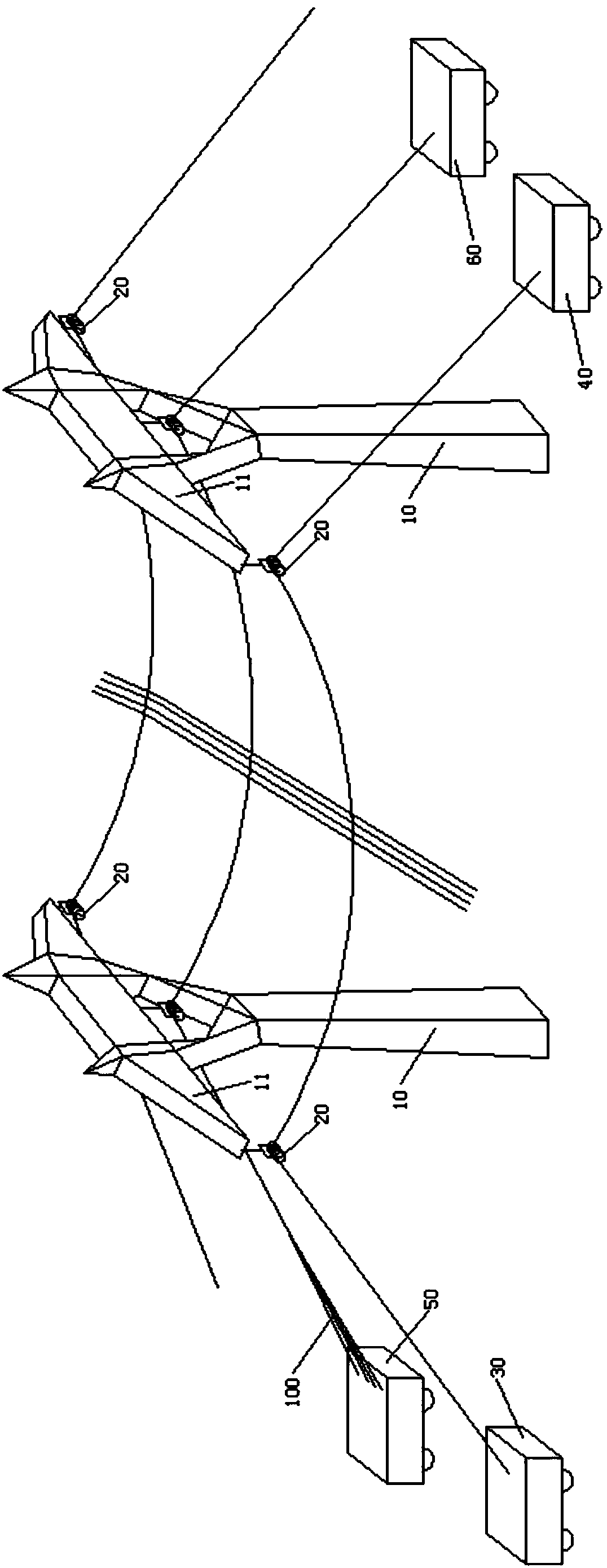
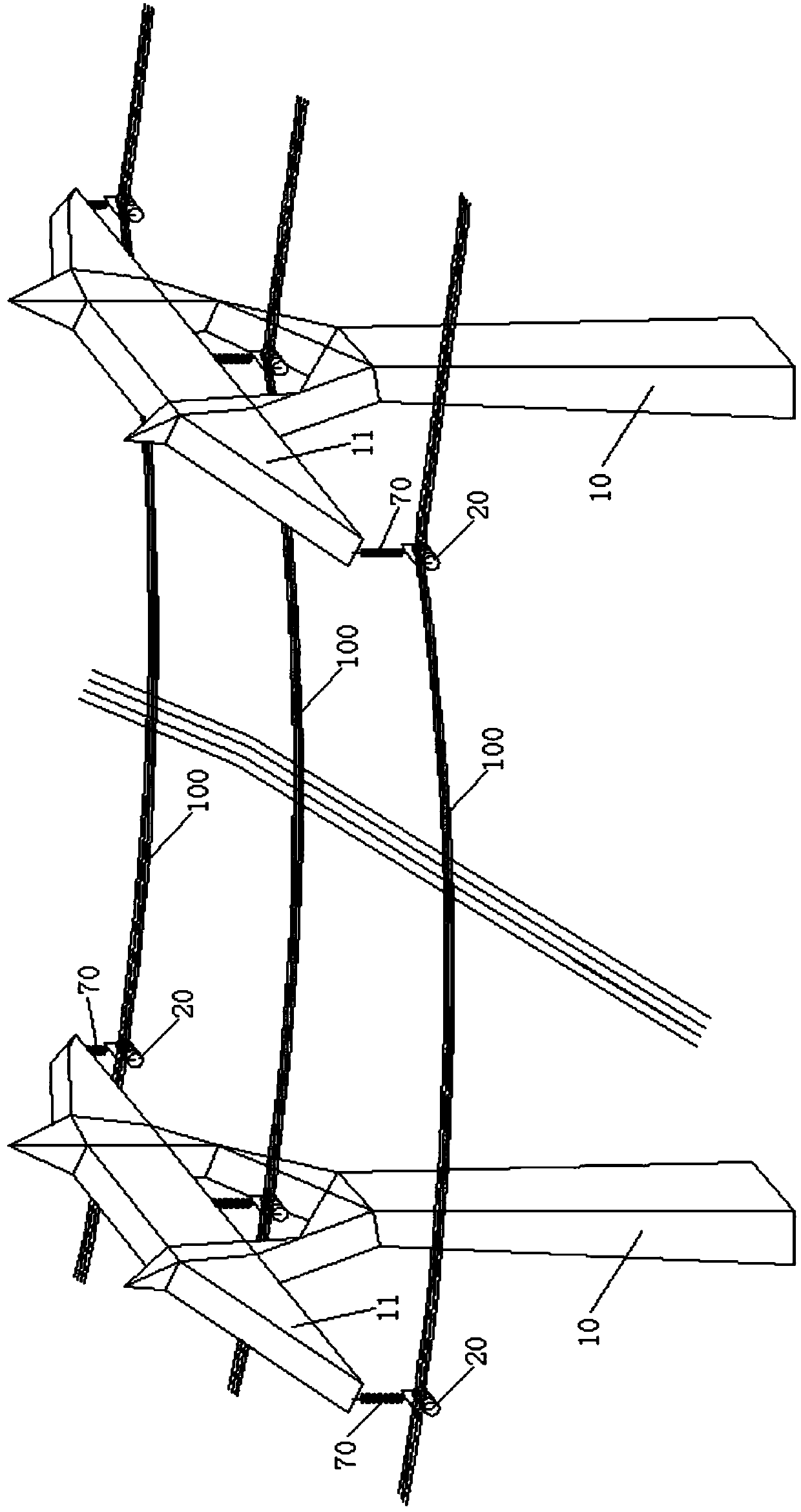
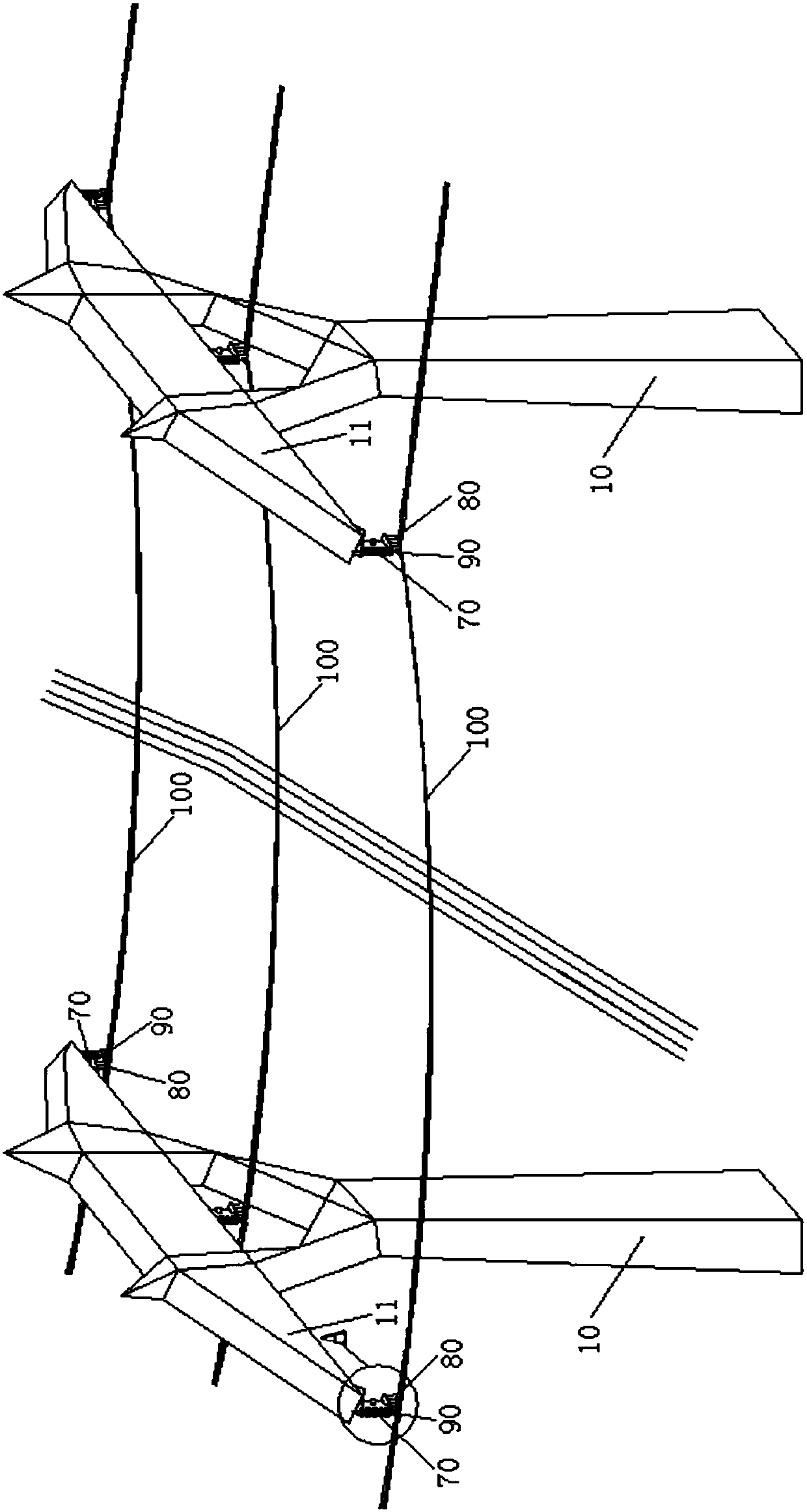
[0032] 1) A cross arm 11 is fixed on the top of the power iron tower 10 where the wire 100 needs to be erected, and a number of pay-off tackles 20 are respectively arranged at the two ends and the center of the cross arm 11, and the pay-off tackle 20 and the cross arm 11 are connected by Metal fittings or 0.5-1 meter long steel rope sets are connected together. In this embodiment, a steel rope sleeve is used to connect the pay-off tackle 20 to the cross arm 11, one end of the steel rope sleeve is connected to the mounting hole of th...


PUM


Abstract

The invention relates to a crossing method for transmission line tension stringing construction. The method comprises the steps that 1) a pay-out pulley is arranged; 2) a guide wire rope is unfolded;3) a load wire rope is unfolded; 4) a wire is unfolded; 5) wire tightening is carried out; 6) an insulator string is arranged, and the pay-out pulley which carries the wire is connected with the insulator string; 7) wire suspending is carried out; and 8) the pay-out pulley is removed, and the wire is fixed on the insulator string. The method provided by the invention is used in the crossing construction of a transmission line. In a pulling process, the overall height of a curve is increased without increasing the unfolding tension of the guide wire rope, the load wire rope and the wire; wire rubbing or touching of crossed power lines, railways, highways, the crossing frames and the like during the pulling process is avoided; the construction safety is ensured, and at the same time the surface quality of the wire is ensured; and the work efficiency is improved.

Description

technical field [0001] The invention belongs to the technical field of power transmission line construction, and in particular relates to a spanning method for tension setting out construction of power transmission lines. Background technique [0002] In recent years, with the rapid development of power grid construction, there have been more and more intersecting and crossing problems in the construction of power lines, forming large-area, multi-point crossing communication lines, railways, highways, viaducts and crossings that have been put into operation Therefore, effectively solving the crossing problem without affecting the normal operation of the crossed object has become an important work content in the construction of transmission line erection. [0003] At present, there are various spanning construction schemes in the power transmission industry, which are mainly divided into two methods: with spanning frame and without spanning frame. Regardless of the method wit...

Claims


Application Information

Patent Timeline
Patent Type & Authority Applications(China)
IPC IPC(8): H02G1/04
CPCH02G1/04
Inventor 江义勇吴金海
Owner ANHUI ELECTRIC POWER TRANSMISSION & TRANSFORMATION ENG
Learn More