Dynamic compensation method and dynamic compensation generating device

A technology of dynamic compensation and generation device, applied in circuit devices, harmonic reduction devices, reactive power adjustment/elimination/compensation and other directions, can solve the problem of long compensation time, limited phase-splitting compensation ability, and can not effectively solve the power quality at the end of the power grid. problems, etc., to achieve the effect of low cost and effective reactive power compensation

Pending Publication Date: 2018-03-23
SUZHOU POWER SUPPLY OF JIANGSU ELECTRIC POWER +1
View PDF2 Cites 12 Cited by
  • Summary
  • Abstract
  • Description
  • Claims
  • Application Information

AI Technical Summary

Problems solved by technology

However, the traditional SVC reactive power compensation device adopts a step-by-step compensation method, and the capacity of each segment is 25kvar or 10kvar. It is easy to cause over-compensation and under-compensation when the capacitor is switched on and off, and the power factor cannot fully meet the standard.
Reactive power compensation for multi-purpose capacitors in the terminal grid, although the power factor is improved, is greatly affected by system harmonics, and it is easy to amplify the harmonics, and the phase-splitting compensation capability is limited, and it can only compensate inductive loads, etc., which is restricted by its own characteristics , cannot effectively solve the power quality problem at the end of the power grid
To sum up, the current low-voltage reactive power compensation mainly adopts the SVC composite switch to control power capacitor switching or smart capacitor (direct) switching methods, which have many shortcomings: (1) The effect of compensation for three-phase unbalanced current is not obvious; (2) ) Harmonic suppression is not ideal; (3) Only step compensation can be performed, which is prone to overcompensation or undercompensation; (4) Compensation time is relatively long, exceeding 100ms
2. SVG does not generate harmonics and will not amplify harmonics. It can filter out more than 50% of harmonics. It has the function of harmonic compensation below 25 times, and the effect of harmonic control is obvious; while the capacitor itself of traditional reactive power compensation devices will be amplified. Harmonics, so there is no way to filter out harmonics
3. SVG can output continuous inductive or capacitive reactive power, stepless compensation starting from 0.1 kilofarads, fully realizes accurate two-way compensation of system reactive power, and there is no problem of over-compensation or under-compensation of capacitor compensation devices; The capacitor compensation device basically uses 3-10 levels of compensation, and each increase or decrease of one level is at least several thousand methods, which cannot achieve accurate compensation.
However, SVG also has certain shortcomings. The biggest problem is the high equipment cost and maintenance cost. If SVG is used to realize large-capacity compensation, its price will be several times higher than that of SVC with the same capacity.
[0007] It can be seen that the two existing compensation methods - SVC and SVG each have different advantages and disadvantages, and a single device cannot solve the compensation problem well

Method used


Image

  • Dynamic compensation method and dynamic compensation generating device
  • Dynamic compensation method and dynamic compensation generating device
  • Dynamic compensation method and dynamic compensation generating device

Examples


Embodiment 1

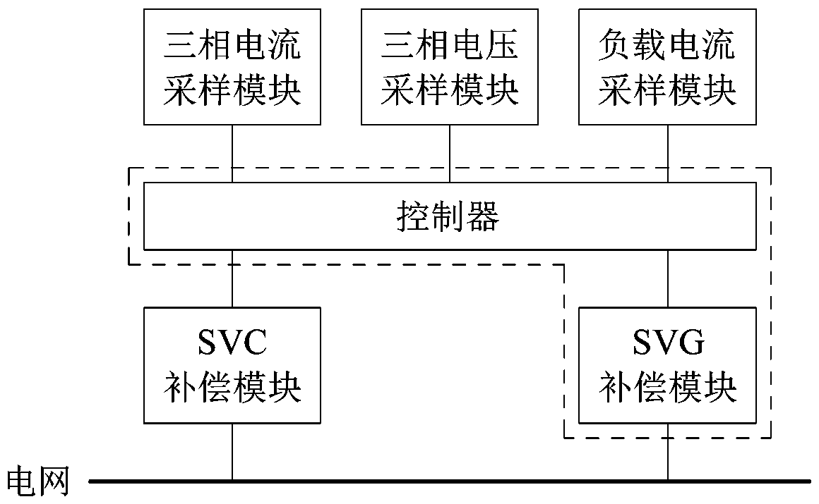
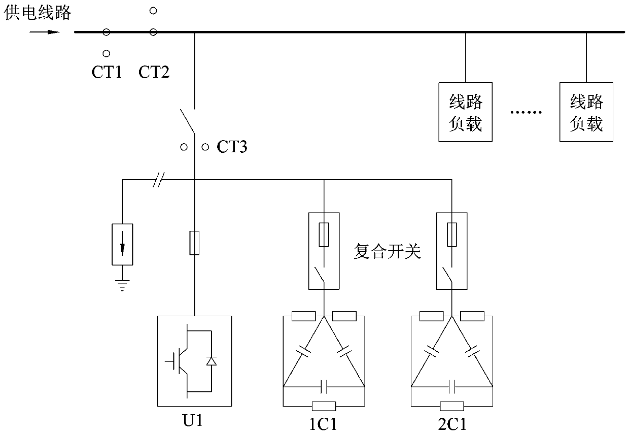
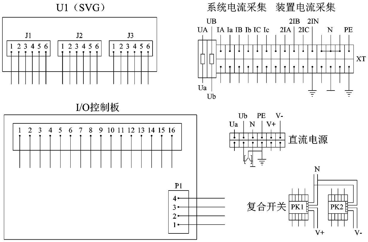
[0037] Embodiment one: as attached figure 1 to attach image 3 As shown in the figure, a dynamic compensation generating device connected to the system composed of the power grid and the load and used for reactive power compensation, three-phase unbalance compensation and voltage instability compensation includes a three-phase current sampling module, a load current sampling module, three Phase voltage sampling module, SVC compensation module, SVG compensation module and controller.

[0038] The three-phase current sampling module is used for sampling the three-phase current in the system, the load current sampling module is used for sampling the load current of the system, and the voltage sampling module is used for sampling the three-phase voltage of the system. The three-phase current sampling module, the load current sampling module, and the three-phase voltage sampling module are all connected to the controller so as to send corresponding sampling signals to the controll...


PUM


Abstract

The invention relates to a dynamic compensation method. The dynamic compensation method comprises the first step of sampling three-phase current, three-phase voltage and load current of a system; thesecond step of judging whether the three-phase current of the system is balanced or not, and judging whether the power factor deviates from a set power factor target value or not, judging whether thethree-phase voltage exceeds a voltage set value or not; step 3, judging whether the three-phase voltage exceeds a voltage set value or not; the third step of calculating the current value required tobe converted by each phase when the three-phase current is unbalanced, calculating the reactive current to be compensated when the calculated power factor of the system deviates from the power factortarget value, and calculating the current used for voltage regulation when the three-phase voltage exceeds the voltage set value; and fourth step of firstly adopting an SVC compensation mode, and thenoutputting compensation current by adopting an SVG compensation mode to compensate the system. The dynamic compensation method is realized through a dynamic compensation generating device. Accordingto the invention, the SVC compensation and the SVG compensation are comprehensively utilized, reactive compensation, and three-phase imbalance compensation and voltage instability compensation are effectively, fast and accurately carried out on a system. The cost is relatively low.

Description

technical field [0001] The invention belongs to the field of power supply and distribution, and in particular relates to a device for dynamically compensating a grid system. Background technique [0002] The extensive use of various modern power facilities, while improving people's lives, also makes the power system more and more polluted, power quality problems such as low power factor, three-phase imbalance, high harmonic content, voltage fluctuation and flicker It seriously threatens the normal operation of power system user equipment. At the same time, the above problems also put forward higher requirements for the existing voltage and reactive power compensation technology. [0003] After the statistical analysis of the monitoring data in the low-voltage distribution network, it is found that the problem of unbalanced three-phase current distribution is common in most of the stations with low power factors. In addition, affected by local governments at all levels to s...

Claims


Application Information

Patent Timeline
Patent Type & Authority Applications(China)
IPC IPC(8): H02J3/18H02J3/26H02J3/12H02J3/01
CPCH02J3/01H02J3/12H02J3/1835H02J3/26Y02E40/50Y02E40/10Y02E40/40
Inventor 孟庆波李笑波杨爱华刘亚辉汪洋张应钊王文聪颜洁
Owner SUZHOU POWER SUPPLY OF JIANGSU ELECTRIC POWER
Why Eureka
Try Eureka